

Whether you’re an electrical engineering student preparing for exams, a technician troubleshooting power systems, or simply curious about how electricity reaches your home – understanding transformers is absolutely essential. Having worked with transformers for over 15 years in manufacturing, I’ve seen countless questions about these devices. In this comprehensive guide, I’ll explain everything you need to know about transformers.
| Key Fact | Detail |
|---|---|
| Invented | 1831 (Faraday’s discovery) |
| First commercial use | 1885 |
| Working principle | Electromagnetic induction |
| Efficiency | Typically 95-99% |
| Power range | From mW to 1000+ MVA |
📋 Table of Contents
What Is a Transformer?
A transformer is a passive electrical device that transfers electrical energy from one circuit to another through electromagnetic induction. Unlike many electrical devices, a transformer has no moving parts – it operates entirely on the principle discovered by Michael Faraday in 1831.
In our factory, we often explain it to customers this way: think of a transformer as a “voltage converter” for AC electricity. It takes the input voltage from the primary side and converts it to a different output voltage on the secondary side – either stepping up (increasing) or stepping down (decreasing) the voltage while keeping the electric power nearly the same.
Basic Components of a Transformer
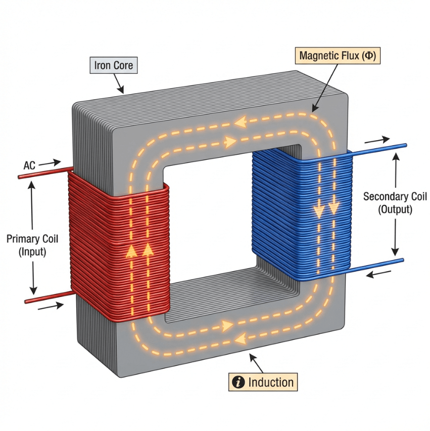
Educational technical 3D illustration of a transformer working principle
Every transformer consists of three essential parts:
| Component | Function |
|---|---|
| Primary Coil (Primary Winding) | Receives the input voltage from the AC source |
| Secondary Coil (Secondary Winding) | Delivers the output voltage to the load |
| Magnetic Core | Provides a path for magnetic flux between coils |
The primary and secondary coils are made of coils of wire (insulated copper or aluminum) wound around the magnetic core. The number of turns in each winding determines the voltage transformation ratio (turns ratio).
Why Transformers Only Work with AC
One question I get asked frequently: “Can a transformer work with DC (direct current)?”
The answer is no – and here’s why. Transformers rely on a changing magnetic field to induce voltage in the secondary winding. When AC flows through the primary coil, it creates a varying magnetic field that induces voltage in the secondary coil. DC produces a constant magnetic field, which cannot induce any voltage in the secondary winding.
This is a fundamental principle that students and new engineers sometimes overlook. During a factory tour last year, a customer asked why their DC-powered equipment couldn’t use a standard transformer – this is the exact reason.
How Does a Transformer Work?
The working principle of a transformer is based on Faraday’s Law of Electromagnetic Induction, discovered in 1831. Let me walk you through the process of how transformers operating in AC circuits transfer energy.
The Working Principle (Step by Step)
- AC Current Enters the Primary Coil
When alternating current flows through the primary winding (also called the primary coil), it creates a magnetic field around the coils of wire. - Magnetic Field Varies with Time
Since AC constantly changes direction (typically 50 or 60 times per second), the magnetic field also continuously varies in strength and direction. - Magnetic Flux Travels Through the Core
The iron core provides a low-reluctance path for the magnetic flux, efficiently channeling it from the primary coil to the secondary coil. In our experience, the quality of the core material significantly affects transformer efficiency. - EMF is Induced in the Secondary Coil
According to Faraday’s Law, a changing magnetic flux through a coil induces an electromotive force (EMF) or voltage in the secondary winding. The secondary coil, wrapped around the same core, experiences this changing flux and generates the output voltage. - Electric Power is Transferred
When a load is connected to the secondary winding, current flows, and electric power is transferred from the primary circuit to the secondary circuit. The voltage in the secondary winding depends on the turns ratio between the primary and secondary coils.
The Formula Behind It
The relationship between the primary and secondary voltages is governed by the turns ratio:
Where:
Vp = Primary voltage
Vs = Secondary voltage
Np = Number of turns in primary winding
Ns = Number of turns in secondary winding
a = Turns ratio
Example Calculation: If a transformer has 1000 turns on the primary and 100 turns on the secondary, with a primary voltage of 220V:
This is a 10:1 step-down transformer.
Ideal vs. Real Transformers
An ideal transformer is a theoretical concept where:
- No energy losses occur
- Perfect magnetic coupling exists between windings
- The core has infinite permeability
In reality, real transformers have:
- Core losses (hysteresis and eddy currents)
- Copper losses (I²R heating in windings)
- Leakage flux (not all flux links both windings)
- Winding resistance
However, well-designed commercial transformers achieve 95-99% efficiency, making them remarkably close to ideal.
Transformer Equations and Formulas
Understanding the mathematical relationships in transformers is essential for proper selection and application. Here are the key formulas every engineer should know:
| Formula | Application |
|---|---|
| Vp/Vs = Np/Ns | Voltage transformation |
| VpIp = VsIs | Power conservation |
| E = 4.44fNΦm | EMF calculation |
| Z’ = a²Z | Impedance matching |
Types of Transformers
Transformers come in many varieties, classified by their construction, application, or operating characteristics.
By Voltage Level
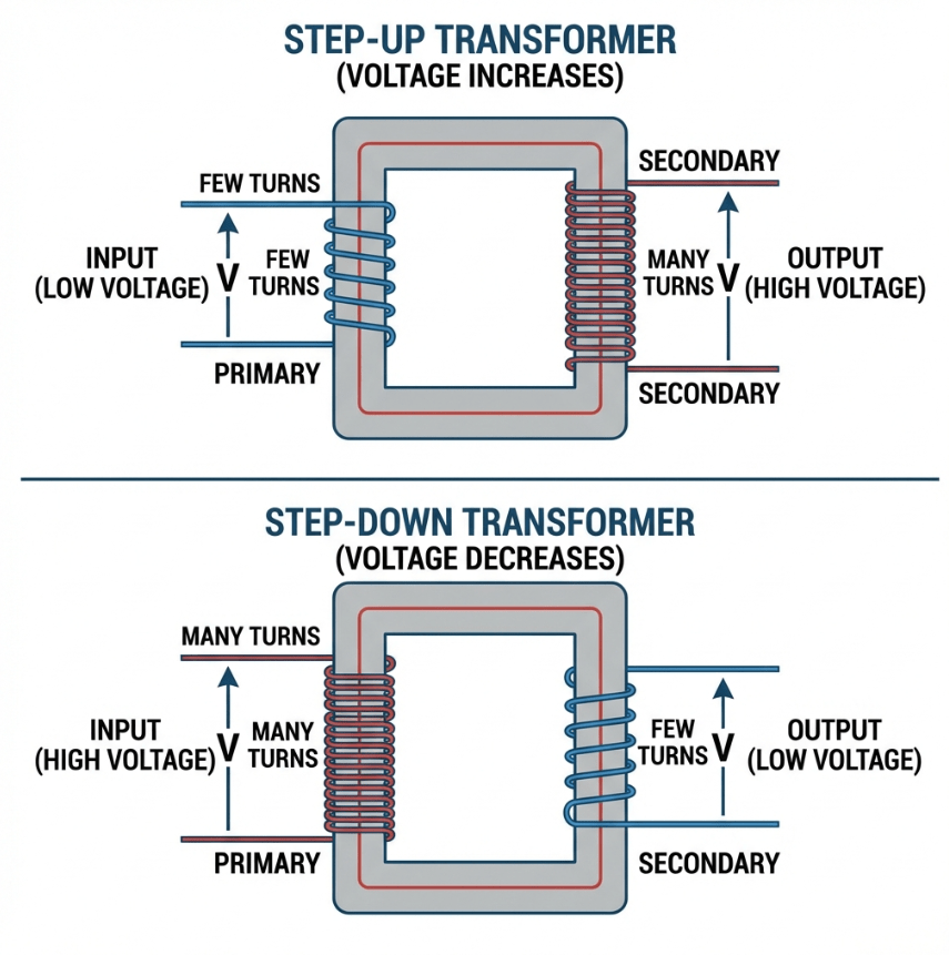
Educational diagram showing Step-Up vs Step-Down Transformer concepts
| Type | Function | Turns Ratio |
|---|---|---|
| Step-Up Transformer | Increases voltage | Np < Ns, a < 1 |
| Step-Down Transformer | Decreases voltage | Np > Ns, a > 1 |
| Isolation Transformer | Same voltage, electrical isolation | Np = Ns, a = 1 |
By Application
| Type | Description | Typical Use |
|---|---|---|
| Power Transformer | High-capacity voltage transformation | Power generation, transmission |
| Distribution Transformer | Deliver power to end users | Pole-mounted, pad-mounted |
| Current Transformer (CT) | Measure high currents | Metering, protection |
| Voltage Transformer (PT) | Measure high voltages | Metering, protection |
| Autotransformer | Single winding with tap | Voltage adjustment, motor starting |
| Isolation Transformers | 1:1 ratio, galvanic isolation | Medical, safety applications |
By Cooling Method
| Designation | Meaning |
|---|---|
| AN | Air Natural (dry-type, self-cooled) |
| AF | Air Forced (dry-type with fans) |
| ONAN | Oil Natural, Air Natural |
| ONAF | Oil Natural, Air Forced |
| OFAF | Oil Forced, Air Forced |
Transformer Construction
Understanding transformer construction helps in selecting the right unit and diagnosing problems.
The Core
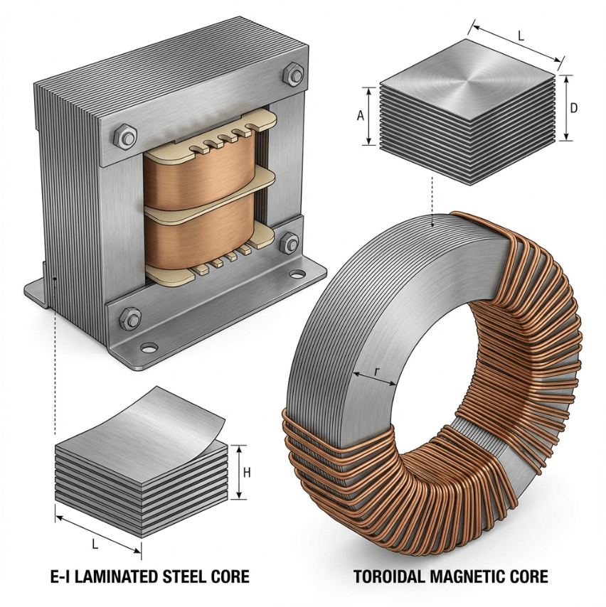
The magnetic core is typically made from grain-oriented silicon steel laminations:
- Lamination – Thin sheets (0.23-0.35mm) reduce eddy current losses
- Silicon content – 3-4% silicon increases resistivity, reducing eddy currents
- Grain orientation – Aligns magnetic domains for lower hysteresis losses
| Core Type | Description | Application |
|---|---|---|
| E-I Core | E and I shaped laminations | Small to medium transformers |
| C-Core | Cut from wound strip | Better efficiency |
| Toroidal | Ring shaped | Audio, low EMI applications |
| Amorphous | Non-crystalline metal | Ultra-low loss distribution |
The Windings
Transformer windings are made from either copper or aluminum conductors:
| Material | Advantages | Disadvantages |
|---|---|---|
| Copper | Better conductivity, smaller size | Higher cost |
| Aluminum | Lower cost, lighter weight | Larger size needed |
Transformer Losses and Efficiency
No transformer is 100% efficient. Understanding losses helps in selecting efficient units and reducing operating costs.
Core Losses (Iron Losses)
Core losses occur in the magnetic core and are constant regardless of load:
- Hysteresis Loss – Caused by constant reversal of magnetic domains
- Eddy Current Loss – Caused by circulating currents in the core
Copper Losses (Winding Losses)
These losses increase with the square of the load current.
Typical Efficiency Values
| Transformer Type | Efficiency |
|---|---|
| Small (<5 kVA) | 95-97% |
| Medium (5-500 kVA) | 97-98% |
| Large (>500 kVA) | 98-99%+ |
| Distribution | 98-99% |
| Power | 99%+ |
Transformer Testing
Proper testing ensures transformer reliability and performance.
| Test | Purpose | When Performed |
|---|---|---|
| Turns Ratio Test | Verify voltage ratio | Factory, commissioning |
| Winding Resistance Test | Check for bad connections | Factory, maintenance |
| Insulation Resistance Test | Check insulation condition | Commissioning, maintenance |
| Open Circuit Test | Measure core losses | Factory |
| Short Circuit Test | Measure copper losses | Factory |
| Oil BDV Test | Oil dielectric strength | Routine maintenance |
| Dissolved Gas Analysis | Detect internal faults | Condition monitoring |
Transformer Applications
Transformers serve countless applications across many industries:
Power System Applications
| Application | Transformer Type | Typical Ratings |
|---|---|---|
| Power Generation | Generator step-up | 400-1000 MVA |
| HV Transmission | Power transformer | 100-500 MVA |
| Distribution | Distribution transformer | 10 kVA – 5 MVA |
| Substation | Substation transformer | 1-60 MVA |
Industrial Applications
- Motor Starting – Autotransformers reduce starting current
- Arc Furnaces – Special high-current transformers
- Welding – Leakage transformers provide current limiting
- Control Circuits – Control transformers provide safe voltages
Special Applications
- Medical Equipment – Isolation for patient safety
- Railway – Traction transformers for trains
- Renewable Energy – Wind and solar inverter transformers
Transformer Maintenance
Proper maintenance extends transformer life and prevents failures.
Routine Inspection Checklist
| Check | Frequency | Action Required |
|---|---|---|
| Oil level | Monthly | Top up if low |
| Oil temperature | Weekly | Investigate if high |
| Silica gel color | Monthly | Replace if pink |
| Unusual noise | Daily | Investigate buzzing |
| Oil leaks | Monthly | Repair immediately |
Common Problems and Solutions
| Problem | Cause | Solution |
|---|---|---|
| Humming noise | Loose core/windings | Re-tighten mounting |
| Overheating | Overload, poor cooling | Reduce load, clean radiators |
| Oil leakage | Gasket failure | Replace gaskets |
| Low oil | Leakage, expansion | Repair leak, top up |
| High moisture | Breather failure | Replace silica gel |
Frequently Asked Questions
Conclusion
Transformers are essential devices that enable our modern electrical infrastructure. Key takeaways from this guide:
- Working Principle: Transformers use electromagnetic induction to transfer energy between circuits
- Types: Many specialized types of transformers exist for different applications
- Efficiency: Modern transformers achieve 95-99%+ efficiency
- Maintenance: Regular inspection and testing extends transformer life
- Selection: Consider voltage, capacity, cooling, and application requirements
Understanding these fundamentals will help you select, operate, and maintain transformers more effectively.
Need Expert Guidance?
Understanding transformer fundamentals is just the beginning. Whether you’re selecting a transformer for a new project or troubleshooting an existing installation, our engineering team can help.
Contact Our Team