
Buck-Boost Transformer: Complete Guide to Wiring, Sizing & Voltage Correction
Your equipment says 240V on the nameplate, but your building only delivers 208V. The motor runs hot, the HVAC unit underperforms, and the lighting is noticeably dim. This is one of the most common voltage mismatch problems in commercial and industrial facilities across North America — and a buck-boost transformer is the simplest, most cost-effective solution.
Quick Answer: A buck-boost transformer is a small, dry-type transformer wired as an autotransformer to raise (“boost”) or lower (“buck”) supply voltage by 5% to 20%. The most common application is boosting 208V to 240V for equipment like HVAC systems, commercial dryers, and motor loads. They are compact, efficient (typically 97–99%), and significantly cheaper than full isolation transformers for minor voltage corrections.
What Is a Buck-Boost Transformer?
A buck-boost transformer is a single-phase, dry-type transformer with dual primary (H1–H4) and dual secondary (X1–X4) windings. While it ships as a standard isolation transformer, it is field-wired as an autotransformer — meaning the primary and secondary windings are electrically connected in series to either add voltage (boost) or subtract voltage (buck) from the supply.
The key characteristics that define a buck-boost transformer:
| Feature | Specification |
|---|---|
| Type | Dry-type, encapsulated |
| Phase | Single-phase (banked for 3-phase) |
| Voltage Correction Range | 5% to 20% of supply voltage |
| Typical Voltage Combos | 120×240V / 12/24V or 240×480V / 24/48V |
| kVA Ratings | 0.05 kVA to 7.5 kVA (nameplate) |
| Enclosure | NEMA 3R (indoor/outdoor) |
| Insulation System | 180°C (Class H) |
| Efficiency | 97–99% when wired as autotransformer |
| Standards | UL Listed, CSA Certified, meets NEMA ST-20 |
How a Buck-Boost Transformer Works (Autotransformer Principle)
When wired as an autotransformer, the buck-boost transformer doesn’t transform the full load power. Instead, it only transforms the difference between the input and output voltage. This is why a transformer with a small nameplate kVA rating can handle a much larger load.
For example, boosting 208V to 240V is a 15.4% voltage increase. The transformer only needs to handle 15.4% of the total load power — the remaining 84.6% passes directly through the winding without being transformed. This is what makes buck-boost transformers so compact and efficient compared to isolation transformers.
The working principle follows the standard transformer voltage ratio:
V₂ / V₁ = N₂ / N₁
Where:
– V₁ = Input (primary) voltage
– V₂ = Output (secondary) voltage
– N₁ = Primary turns
– N₂ = Secondary turns
In autotransformer configuration, the secondary winding is connected in series with the primary, adding (boost) or subtracting (buck) voltage from the supply.
Buck vs Boost: Understanding Voltage Direction
The terms “buck” and “boost” describe the direction of voltage correction:
| Mode | Action | Wiring | Example |
|---|---|---|---|
| Boost | Increases voltage | Secondary adds to primary | 208V → 240V |
| Buck | Decreases voltage | Secondary subtracts from primary | 240V → 208V |
The direction depends entirely on how you connect the secondary winding terminals (X1–X4) relative to the primary (H1–H4). Reversing the secondary connections switches between buck and boost mode. This is why polarity matters critically — a wiring mistake can cause the transformer to buck when you intended to boost, resulting in even lower output voltage.
Autotransformer kVA vs Nameplate kVA — What’s the Difference?
This is one of the most misunderstood aspects of buck-boost transformers, and it’s something that frequently causes confusion during the sizing process.
The nameplate kVA is the transformer’s rating when used as an isolation transformer (primary and secondary completely separate). The autotransformer kVA is the actual load capacity when field-wired as an autotransformer — and it’s always much higher than the nameplate rating.
The relationship is:
Autotransformer kVA = Nameplate kVA × (V_output / V_boost)
Where V_boost is the voltage added by the secondary winding.
Practical example:
– Nameplate: 1 kVA
– Application: Boost 208V to 240V
– V_boost = 240V – 208V = 32V
– Autotransformer kVA = 1 kVA × (240V / 32V) = 7.5 kVA
A 1 kVA nameplate buck-boost transformer can actually handle a 7.5 kVA load when boosting 208V to 240V. This is why these small, lightweight units can power substantial loads.
When to Use a Buck-Boost Transformer (And When NOT To)
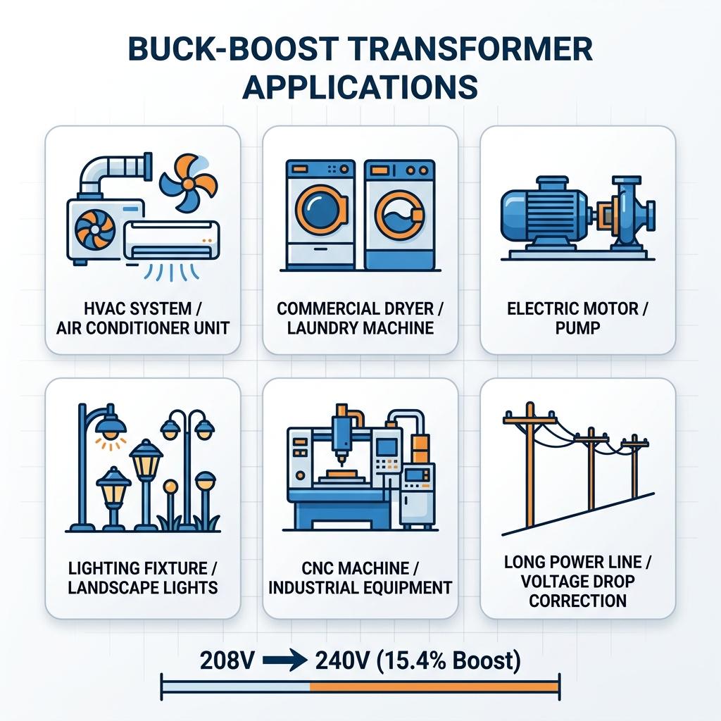
Ideal Applications
Buck-boost transformers are the right choice when you need a small, consistent voltage adjustment and electrical isolation is not required:
- HVAC systems & mini-splits — 208V supply feeding 240V rated compressors
- Commercial dryers & ovens — 208V buildings with 240V appliances
- Motor loads — Correcting low voltage that causes overheating and reduced torque
- Lighting systems — Low-voltage landscape and interior lighting circuits
- CNC machines & pumps — Equipment rated for 240V in 208V facilities
- Voltage drop compensation — Long feeder circuits with excessive voltage drop
In our experience working with commercial facilities, the 208V to 240V mismatch is by far the most common scenario. Many commercial buildings in North America receive 120/208V three-phase wye service, but much of the equipment — particularly HVAC units, electric dryers, and motor-driven machinery — is rated for 240V. Without correction, a 240V-rated resistance heating element operating at 208V produces only about 75% of its rated heat output, which significantly impacts drying times and heating efficiency.
Limitations You Must Know Before Buying
A buck-boost transformer is NOT suitable for:
| Limitation | Explanation |
|---|---|
| Large voltage changes | Cannot handle transformations like 120V → 480V. Only 5–20% correction. |
| Voltage regulation/stabilization | Does NOT regulate fluctuating voltages. Input varies → output varies proportionally. |
| Electrical isolation | Autotransformer wiring provides NO galvanic isolation between input and output. |
| Phase conversion | Cannot convert single-phase to three-phase or vice versa. |
| Frequency conversion | Cannot change 50Hz to 60Hz or vice versa. |
| Sensitive electronics | Equipment requiring clean, isolated power (medical devices, precision instruments) needs an isolation transformer instead. |
| Creating a neutral | Cannot create a neutral conductor where none exists in the supply. |
Buck-Boost Transformer vs Isolation Transformer — Key Differences
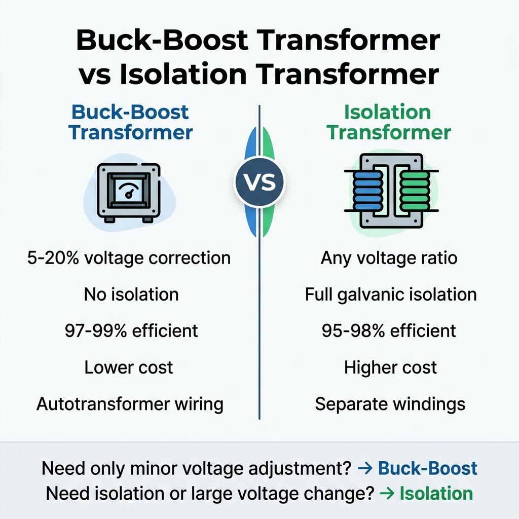
One of the most common questions we encounter is whether to use a buck-boost transformer or a standard isolation transformer. Here’s a detailed comparison:
| Parameter | Buck-Boost Transformer | Isolation Transformer |
|---|---|---|
| Wiring Configuration | Autotransformer (windings connected) | Two separate windings |
| Electrical Isolation | ❌ No isolation | ✅ Full galvanic isolation |
| Voltage Adjustment Range | 5–20% only | Any ratio (e.g., 480V → 120V) |
| Size & Weight | Compact and lightweight | Larger and heavier for same load |
| Cost | Significantly lower (up to 75% less) | Higher due to more copper and iron |
| Efficiency | 97–99% | 95–98% |
| Noise Suppression | Minimal | Good common-mode noise rejection |
| NEC Classification | NEC 450.4 (Autotransformer) | NEC 450.3 (Transformer) |
| Best For | Minor voltage correction | Full voltage transformation, safety isolation |
Rule of thumb: If you only need to adjust voltage by 5–20% and don’t need isolation, use a buck-boost transformer. For anything else, use an isolation transformer or a standard step-up / step-down transformer.
Understanding 208V vs 240V — Why This Voltage Mismatch Exists
120/208V Wye Systems vs 120/240V Split-Phase
The 208V vs 240V confusion stems from two different electrical service configurations common in North America:
| Service Type | Configuration | Line-to-Neutral | Line-to-Line | Common In |
|---|---|---|---|---|
| 120/240V Split-Phase | Single-phase, center-tapped | 120V | 240V | Residential homes |
| 120/208V Three-Phase Wye | Three-phase, 4-wire wye | 120V | 208V | Commercial buildings, offices |
In a three-phase wye system, the line-to-line voltage is 120V × √3 = 208V, not 240V. This creates a 32V (15.4%) deficit for equipment rated at 240V.
How a 15% Voltage Difference Affects Equipment Performance
The impact of running 240V equipment on 208V is more significant than most people realize:
| Equipment Type | Effect at 208V (vs 240V) | Impact |
|---|---|---|
| Resistance heaters | Power output drops to ~75% (P = V²/R) | 25% longer heating/drying times |
| Motors | Current increases, torque decreases | Overheating, shortened lifespan |
| Lighting (incandescent) | Reduced brightness (~25% less lumens) | Dim, yellowish light |
| Compressors (HVAC) | Reduced cooling capacity | System struggles on hot days |
| Electronic power supplies | May operate within tolerance | Usually acceptable |
For resistance loads, the power reduction follows the square of the voltage ratio: (208/240)² = 0.751, meaning only 75.1% of rated power output. This is why a commercial dryer that works perfectly in a residential 240V home takes significantly longer to dry clothes in a 208V commercial building.
How to Wire a Buck-Boost Transformer (208V to 240V)
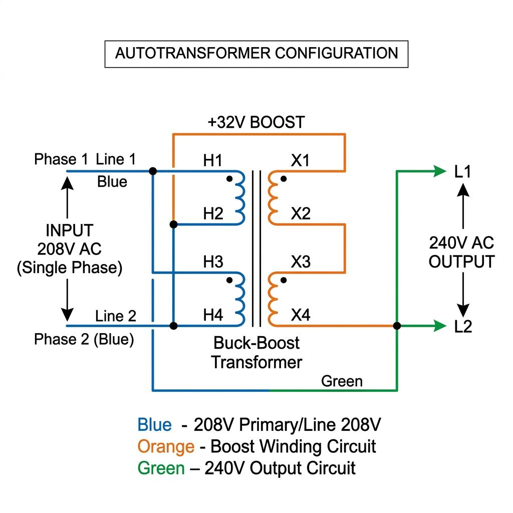
⚠️ Safety Warning: All electrical work involving buck-boost transformers must be performed by a qualified, licensed electrician in compliance with the National Electrical Code (NEC) and local regulations. Always de-energize circuits before making connections and verify output voltage with a multimeter before connecting any load.
Single Phase Wiring: 208V Input → 240V Output (Step-by-Step)
To boost single-phase 208V to 240V, you need a buck-boost transformer with 120×240V primary / 16/32V secondary windings (most common: 240×480V / 24/48V rated units).
Step 1: Identify all terminals on the transformer nameplate:
– Primary: H1, H2, H3, H4
– Secondary: X1, X2, X3, X4
Step 2: Connect the primary windings in parallel for 240V operation:
– Connect H1 to H3
– Connect H2 to H4
Step 3: Connect the secondary windings in series for 32V boost:
– Connect X2 to X3
Step 4: Make the autotransformer connections:
– Connect LINE 1 (208V) to H1
– Connect H2 to X1
– Connect LINE 2 (208V) to X4
– OUTPUT is taken from H1 and X4
Step 5: Verify output voltage:
– With no load connected, measure voltage between H1 and X4
– Expected reading: approximately 236–242V (208V + 32V boost)
Terminal Identification: H1, H2, H3, H4, X1, X2, X3, X4
| Terminal | Function |
|---|---|
| H1, H2 | Primary winding 1 |
| H3, H4 | Primary winding 2 |
| X1, X2 | Secondary winding 1 |
| X3, X4 | Secondary winding 2 |
Polarity Matters — Why Reversing Connections Bucks Instead of Boosts
The secondary winding must be connected with the correct polarity to add voltage to the supply. If you reverse the secondary connections, the secondary voltage subtracts from the primary, and your 208V input becomes approximately 176V output — exactly the opposite of what you intended.
How to check: Always verify output voltage with a multimeter before connecting any load. If the output is lower than the input, you have the secondary polarity reversed.
Important: Every manufacturer includes specific wiring diagrams with their buck-boost transformers. Always follow the manufacturer’s diagram for your specific model. The general steps above are for educational purposes — connection configurations vary between manufacturers such as Eaton, Hammond Power Solutions, Schneider Electric (Square D), and Acme Electric.
Three-Phase Buck-Boost Connections
Buck-boost transformers are single-phase devices. For three-phase voltage correction, you must bank multiple units together. There are three standard configurations:
Open Delta (2-Unit) Configuration
Uses 2 single-phase buck-boost transformers connected in open delta. This is the most economical three-phase option but provides only 86.6% of the capacity of a closed delta bank.
Best for: Lighter three-phase loads where cost savings outweigh the reduced capacity.
Wye (3-Unit) Configuration
Uses 3 single-phase buck-boost transformers, each connected between one phase and the neutral. This requires a 4-wire (wye with neutral) supply.
Best for: 120/208V wye systems that need to be boosted to 277/480V or similar configurations where a neutral is available.
Closed Delta (3-Unit) Configuration
Uses 3 single-phase buck-boost transformers connected in a closed delta configuration. Provides full rated capacity and is the most robust three-phase option.
Best for: Heavy three-phase loads requiring maximum capacity and balanced voltage correction across all phases.
Buck-Boost Transformer Sizing Guide
How to Calculate Required kVA
Sizing a buck-boost transformer requires calculating the nameplate kVA needed, not the load kVA. Follow these steps:
Step 1: Determine the load current (amps) on the circuit.
Step 2: Calculate the voltage boost required:
– V_boost = V_output – V_input
– Example: 240V – 208V = 32V
Step 3: Calculate nameplate kVA:
– Single-phase: Nameplate kVA = (V_boost × Load Amps) / 1000
– Three-phase: Nameplate kVA = (V_boost × Load Amps × √3) / 1000
Example: A 208V to 240V boost for a 50A single-phase load:
– V_boost = 32V
– Nameplate kVA = (32V × 50A) / 1000 = 1.6 kVA
– Select the next standard size: 2 kVA nameplate buck-boost transformer
Sizing Chart by Load Amps (208V → 240V Boost, Single Phase)
| Load Amps | V_boost | Required Nameplate kVA | Standard Size | Autotransformer kVA |
|---|---|---|---|---|
| 10A | 32V | 0.32 kVA | 0.50 kVA | 3.75 kVA |
| 20A | 32V | 0.64 kVA | 0.75 kVA | 5.63 kVA |
| 30A | 32V | 0.96 kVA | 1.0 kVA | 7.50 kVA |
| 40A | 32V | 1.28 kVA | 1.5 kVA | 11.25 kVA |
| 50A | 32V | 1.60 kVA | 2.0 kVA | 15.00 kVA |
| 75A | 32V | 2.40 kVA | 3.0 kVA | 22.50 kVA |
| 100A | 32V | 3.20 kVA | 5.0 kVA | 37.50 kVA |
Pro Tip: When using the KVA to Amps calculator to determine your load current, always use the actual measured current rather than the equipment nameplate rating. Nameplate ratings represent maximum draw, and actual operating current is often 70–80% of the rated value.
Standard Voltage Combinations & Applications
Buck-boost transformers can handle a variety of voltage corrections depending on how the windings are connected:
| Input Voltage | Output Voltage | Change | Direction | Typical Application |
|---|---|---|---|---|
| 208V | 240V | +15.4% | Boost | HVAC, dryers, motors in commercial buildings |
| 240V | 208V | –13.3% | Buck | Equipment from 240V sites used in 208V buildings |
| 120V | 132V | +10% | Boost | Low-voltage landscape lighting correction |
| 240V | 264V | +10% | Boost | Compensating voltage drop on long feeders |
| 277V | 240V | –13.4% | Buck | Converting 277V lighting circuits for 240V loads |
| 480V | 440V | –8.3% | Buck | Imported machinery rated for 440V |
| 440V | 480V | +9.1% | Boost | Older equipment on modern 480V systems |
NEC Code Requirements for Buck-Boost Transformers
Understanding the National Electrical Code requirements is essential for a safe, code-compliant installation. Buck-boost transformers wired as autotransformers fall under specific NEC articles.
NEC Article 450.4 — Autotransformer Protection
When a buck-boost transformer is field-connected as an autotransformer, it is classified under NEC Article 450.4, not 450.3 (which covers standard transformers). Key requirements include:
- Each autotransformer must have an individual overcurrent protection device (OCPD) on the primary side
- The OCPD must be in series with each ungrounded input conductor
- NEC 450.4(A) specifically prohibits placing an OCPD in series with the shunt winding (the common winding shared by input and output)
Overcurrent Device (OCPD) Sizing
To properly size the OCPD:
- Determine the autotransformer kVA rating (not the nameplate kVA)
- Calculate the full-load input current: I = Autotransformer kVA × 1000 / V_input
- Size the OCPD per NEC requirements for autotransformers
Example: A buck-boost with 7.5 kVA autotransformer rating at 208V input:
– Full-load current = 7,500 / 208 = 36.1A
– OCPD = Next standard size above 36.1A = 40A breaker
Installation & Grounding Requirements
Per NFPA 70 (NEC) and IEEE C57.12:
- Install in a well-ventilated, dry location accessible for maintenance
- NEMA 3R enclosure minimum for outdoor installations
- Proper grounding and bonding per NEC Article 250
- Maintain manufacturer-specified clearances for heat dissipation
- Ensure the transformer is UL Listed and rated for the application voltage
Common Installation Mistakes & Troubleshooting
Wrong Polarity (Bucking Instead of Boosting)
Symptom: Output voltage is lower than input voltage (e.g., 176V output from 208V input instead of 240V).
Cause: Secondary winding connections are reversed.
Fix: Swap the X1 and X4 connections (or X2 and X3, depending on configuration). Always verify with a multimeter before connecting the load.
Oversized or Undersized Unit
Symptom (undersized): Transformer runs excessively hot, audible buzzing increases, may trip overcurrent protection.
Symptom (oversized): No operational problems, but you’ve spent more money than necessary and the unit occupies more space.
Fix: Recalculate the required nameplate kVA using the sizing formula above. Remember to use nameplate kVA (not autotransformer kVA) when ordering.
120V Component Damage from Boosted Voltage
Symptom: Control circuits, timers, drum motors, or displays fail prematurely on equipment that uses both 240V and 120V internally.
Cause: In many appliances (especially dryers and HVAC units), the heating element runs on 240V line-to-line, but the controls, timer motor, and displays run on 120V line-to-neutral. If the buck-boost transformer is connected to the wrong line, the 120V components receive elevated voltage (approximately 130V or more), which can damage them over time.
Fix: Ensure the buck-boost transformer is connected to the line conductor that does not feed the 120V control circuits. Consult the equipment’s wiring diagram to identify which line feeds the 120V components.
Top Buck-Boost Transformer Manufacturers
When selecting a buck-boost transformer, these are the most widely recognized and trusted manufacturers in North America:
| Manufacturer | Notable Products | Strengths |
|---|---|---|
| Eaton | S20, S29, S48 series | Buck-boost calculator tool, extensive design guides, wide distribution |
| Hammond Power Solutions | BK series | Canadian manufacturer, comprehensive technical documentation |
| Schneider Electric (Square D) | S1F, S33 series | Integration with Square D panels, strong technical support |
| Acme Electric | T-series | Long industry heritage, competitive pricing |
All four manufacturers offer UL Listed, CSA Certified units that meet NEMA ST-20 standards. Selection typically comes down to local distributor availability and price.
FAQ — Buck-Boost Transformer
What is a buck-boost transformer used for?
A buck-boost transformer is used to make minor voltage adjustments (5–20%) to match equipment voltage requirements with the available supply voltage. The most common use is boosting 208V to 240V in commercial buildings.
Can a buck-boost transformer convert 120V to 240V?
No. A buck-boost transformer is designed for small voltage adjustments (5–20%), not large transformations. Converting 120V to 240V requires a standard step-up transformer.
What size buck-boost transformer do I need for 208V to 240V?
Calculate the required nameplate kVA: multiply the voltage boost (32V) by the load current (amps) and divide by 1000. For example, a 50A load needs a 1.6 kVA nameplate unit — select the next standard size (2 kVA).
Is a buck-boost transformer the same as an autotransformer?
Not exactly. A buck-boost transformer is shipped as a standard isolation transformer with separate primary and secondary windings. It becomes an autotransformer only when field-wired with the windings connected in series. This distinction matters for code compliance.
Does a buck-boost transformer provide isolation?
No. When wired as an autotransformer (which is the standard configuration), there is no electrical isolation between the input and output circuits. If you need isolation, use a standard isolation transformer.
Can I use a buck-boost transformer to stabilize fluctuating voltage?
No. A buck-boost transformer provides a fixed voltage boost or buck. If the input voltage fluctuates, the output will fluctuate by the same amount. For voltage stabilization, you need a voltage regulator or automatic tap-changing transformer.
How efficient is a buck-boost transformer?
When wired as an autotransformer, efficiency typically ranges from 97% to 99%, which is significantly higher than standard isolation transformers. This high efficiency is because only a small portion of the load power is actually transformed.
Can I use a single buck-boost transformer for three-phase loads?
No. Buck-boost transformers are single-phase devices. For three-phase applications, you need to bank 2 units (open delta) or 3 units (wye or closed delta configuration).
What NEC article covers buck-boost transformer installation?
When field-wired as an autotransformer, buck-boost transformers fall under NEC Article 450.4 for overcurrent protection requirements. Standard transformers (non-autotransformer configuration) fall under NEC 450.3.
How long does a buck-boost transformer last?
With proper installation and adequate ventilation, a quality buck-boost transformer typically lasts 20 to 30 years. The 180°C (Class H) insulation system and encapsulated design provide excellent protection against moisture and environmental contaminants.
Conclusion
A buck-boost transformer is one of the most practical and cost-effective solutions for correcting minor voltage mismatches in commercial and industrial settings. Whether you’re boosting 208V to 240V for an HVAC system or compensating for voltage drop on a long feeder, understanding the proper sizing, wiring, and code requirements ensures a safe, efficient installation.
Key takeaways:
- Buck-boost transformers correct voltage by 5–20% — they are NOT for large voltage transformations
- Always calculate using nameplate kVA, not autotransformer kVA, when ordering
- Polarity is critical — verify output voltage before connecting any load
- NEC 450.4 governs overcurrent protection for autotransformer configurations
- For three-phase loads, bank 2 or 3 single-phase units in delta or wye
Related Articles
- Auto Transformer: Complete Guide to Working, Types & Applications
- Isolation Transformer: Complete Guide to Safety, Noise Reduction & Applications
- Three Phase Transformer: Complete Guide to Connections, Configurations & Applications
- Transformer Protection: Complete Guide to Protection Systems & Relays
- KVA to Amps Calculator: Free 3-Phase & Single-Phase Conversion Tool
- Delta Transformer Diagram: A Technician’s Guide to 3-Phase Connections
- Transformer Troubleshooting: Complete Guide to Common Problems & Solutions
- Transformer Full Load Amps Chart: Complete FLA Reference
- How to Test a Transformer: 8 Essential Tests with Step-by-Step Procedures
- Inside Corner Grounded Delta: Voltage Risks & NEC Safety Rules