
When I first started working in transformer manufacturing, I made a rookie mistake that cost us acustomer callback. I sized a transformer using the ideal model from my textbooks—perfect turns ratio, nolosses, simple calculations. On paper, it was flawless. In real life, that transformer ran hot enough totrigger thermal protection within weeks.That experience taught me something every engineer eventually learns: an ideal transformer doesn’t exist in real life. It’s a theoretical concept that simplifies analysis but can mislead you during actual design. A practical transformer always has losses in the transformer—from winding resistance to core inefficiencies—that you simply cannot ignore.This article covers the 5 key differences between an ideal transformer and a real transformer, complete with calculations, factory experience, and practical guidance on when to use each model.
⚡ Quick Answer
An ideal transformer is a theoretical model with 100% efficiency and zero energy losses
that cannot exist in real life. A real (practical) transformer has winding resistance,
core losses, and leakage flux, resulting in 95-99% typical efficiency. Use the ideal model for
simplified
circuit analysis; use the real model for actual transformer selection and design.
Ideal Transformer vs Real Transformer: 12 Key Differences at a Glance
| Characteristic | Ideal Transformer | Real (Practical) Transformer |
|---|---|---|
| Winding Resistance | Zero | Finite resistance (R₁, R₂) |
| Iron/Core Losses | Zero | Present (eddy current + hysteresis) |
| Copper Losses | Zero | I²R losses in windings |
| Leakage Flux | None (100% coupling) | ~5% of mutual flux |
| Efficiency | 100% | 95-99% typical |
| Magnetizing Current | Zero | 2-5% of rated current |
| Core Permeability | Infinite | Finite value |
| Voltage Regulation | 0% | 2-5% under load |
| Existence | Theoretical only | Physical products |
| Power Equation | Pᵢₙ = Pₒᵤₜ | Pᵢₙ = Pₒᵤₜ + Losses |
| Application | Circuit analysis | Real-world applications |
| Design Considerations | None | Cooling, materials, cost |

What Is an Ideal Transformer?
An ideal transformer is a theoretical model used in electrical engineering to simplify
the analysis of transformer circuits. It represents a perfect energy transfer device that cannot exist
in
real conditions.
The 4 Core Assumptions
- Zero Winding Resistance: The primary and secondary windings have no electrical
resistance. - No Leakage Flux: 100% of the magnetic flux links both the primary and secondary
windings. - No Core Losses: No eddy current or hysteresis losses in the transformer core.
- Infinite Core Permeability: Zero magnetizing current required to establish flux.
The Ideal Transformer Equations
Voltage Ratio:
Current Ratio:
Power Conservation:
These equations form the foundation of transformer
formula calculations, but they only tell part of the story.
What Is a Real (Practical) Transformer?
A real transformer (also called a practical transformer) is what we manufacture,
install,
and use every day. Unlike the ideal model, a real transformer has energy losses that affect performance
and
efficiency.
Real Transformer = Ideal Transformer + Energy Losses
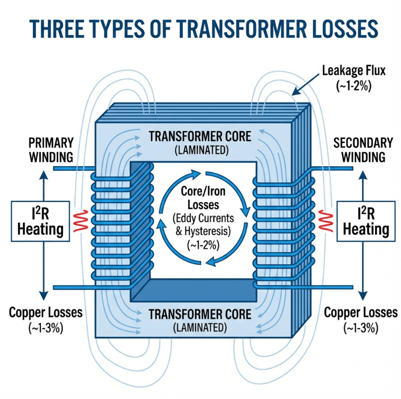
Three Types of Losses in Real Transformers
1. Iron Losses (Core Losses)
Eddy Current Loss: Local circulating currents induced in the core material.
Manufacturers
reduce this by using laminated steel sheets with insulating varnish.
Hysteresis Loss: Energy lost due to the magnetization and demagnetization cycle.
2. Copper Losses (I²R Losses)
- Primary copper loss: Pcu₁ = I₁² × R₁
- Secondary copper loss: Pcu₂ = I₂² × R₂
Copper losses are load-dependent—at 50% load, copper losses are only 25% of their full-load value.
3. Leakage Reactance
Not all flux links both primary and secondary windings. Some leakage flux passes through
air or insulation, creating leakage reactance (X₁ and X₂). Typical leakage flux is about 5% of the
mutual
flux.
The 5 Key Differences Explained
Difference 1: Winding Resistance
Ideal: Zero resistance, purely inductive windings
Real: Copper conductors have finite resistance, causing I²R heating and voltage drop.
Difference 2: Core Losses
Ideal: No eddy currents or hysteresis losses
Real: Core losses are typically 0.5-2% of rated power
difference. An efficiently designed core runs warm to the touch (40-50°C), while poor designs run
noticeably hotter. The hum you hear from a transformer is partly due to magnetostriction.
Difference 3: Leakage Flux
Ideal: 100% of flux links both windings (perfect magnetic coupling)
Real: About 95% coupling efficiency, with 5% leakage flux
Difference 4: Efficiency
Ideal: 100% (all input power delivered to output)
Real: 95-99% for well-designed power transformers
Difference 5: Magnetizing Current
Ideal: Zero (infinite permeability requires no MMF)
Real: 2-5% of rated current, even at no load
Practical Calculation Example
Problem: Calculate Real Transformer Efficiency
A 10 kVA single-phase transformer has:
- Iron loss (constant): 150W
- Full-load copper loss: 200W
- Power factor: 1.0 (unity)
Calculate the efficiency at full load.
Key Point: An ideal transformer analysis would give 100% efficiency. The real
calculation
shows 96.6%—a 3.4% difference that translates to 350W of continuous heat dissipation requiring cooling.
Factory Experience: What the Textbooks Don’t Tell You
transformer beyond the nameplate.
The Sound Test
A quiet hum at line frequency indicates proper core assembly. Buzzing or rattling suggests loose
laminations or mounting issues—signs of a practical transformer problem you won’t find in any ideal
model.
The Touch Test
A well-designed transformer runs warm, typically 40-60°C above ambient. If you can’t comfortably hold
your
hand on the case for 3 seconds, something’s wrong.
Real Case: Why Ideal Models Can Fail You
A customer once called asking why their “correctly sized” step-down
transformer
kept tripping thermal protection. They used ideal model thinking and ignored motor starting currents and
low power factor. The fix: upgrading to the next kVA rating.
When to Use Each Model
| Scenario | Model to Use | Why |
|---|---|---|
| Textbook circuit analysis | Ideal | Simplifies calculations for learning |
| PE/FE exam basic problems | Ideal | Tests fundamental understanding |
| Actual transformer sizing | Real | Must account for losses |
| Efficiency calculations | Real | Ideal gives meaningless 100% |
| Thermal design | Real | Losses = Heat |
| Fault current analysis | Real | Impedance affects short-circuit current |
Frequently Asked Questions
windings (violates physics), no magnetic losses (requires perfect core materials), and infinite
permeability (doesn’t exist).
conductors. When current flows through resistance, power is dissipated as heat according to P = I²R.
high-grade silicon steel (CRGO), minimizing air gaps, and operating at appropriate flux densities.
transformers typically range from 95-98%.
affects regulation, and limits short-circuit strength. However, some leakage reactance is beneficial
for limiting inrush and fault currents.
📌 Key Takeaways
- Ideal transformer = theoretical model, 100% efficiency, zero losses
- Real transformer = practical device, 95-99% efficiency, has losses
- Three main losses: Core (iron), Copper (I²R), Leakage reactance
- Core losses are constant; copper losses increase with load
- Use ideal model for learning and analysis
- Use real model for design, selection, and troubleshooting
Need Help Selecting the Right Transformer?
Understanding real vs ideal transformers is just the start. Our engineering team considers all real-world
factors—efficiency, losses, thermal performance—to recommend the perfect solution for your application.
References
- Wikipedia – Transformer (Ideal Transformer Section)
- Faraday’s Law of Electromagnetic Induction
- Electrical Academia – Ideal Transformer Theory
- Study Electrical – Ideal and Practical Transformer
- Electrical4U – Leakage Reactance and Impedance