
By Tan, Electrical Engineer @Transformer4U | Updated: January 22, 2026
⚡ Quick Answer
Winding faults are the “heart attacks” of transformers. They often happen suddenly due
to mechanical shock (short circuits) or gradually due to insulation failure.
The “Big Three” diagnostic tests are:
- Winding Resistance: Detects loose connections and broken strands (>5% deviation is
bad). - Turns Ratio (TTR): Detects shorted turns (IEEE limit: ±0.5%).
- SFRA (Frequency Response): The gold standard for detecting mechanical deformation
(buckling/telescoping).
inside your transformer during an external short circuit fault. If the winding isn’t perfectly tight and
mechanically robust, it will buckle, twist, or collapse.In my years analyzing failures, I’ve seen massive High Voltage windings twisted like pretzels. The worst
part? The transformer might still energize and run for weeks after the event, hiding the ticking time
bomb inside until it fails catastrophically.
This guide explains how to detect these hidden mechanical and electrical winding faults before they
destroy
your asset.
Understanding Your Transformer’s Anatomy
Not all windings are created equal. The vulnerability of your unit depends heavily on its construction
type.

Common transformer winding configurations: Cylindrical, Helical, and Continuous Disc
| Winding Type | Typical Application | Common Failure Mode |
|---|---|---|
| Cylindrical (Layer) | Small Distribution / HV | Layer-to-layer insulation breakdown |
| Helical | Low Voltage, High Current | Tilting of conductors due to axial forces |
| Continuous Disc | High Voltage Power (>33kV) | Buckling (radial collapse) during short circuits |
The 5 Main Types of Winding Faults
Winding faults generally fall into electrical (insulation) or mechanical (deformation) categories.

Diagram illustrating shorted turns, open circuits, axial displacement, and radial buckling
1. Inter-Turn Short Circuit
This is the most frequent electrical fault. The enamel or paper insulation between two adjacent turns
fails. This creates a closed loop that acts like a short-circuited secondary winding, inducing massive
currents and heat in that localized spot, eventually melting the copper.
2. Winding Deformation (Buckling/Telescoping)
Caused by electromagnetic forces during faults. “Hoop stress” tries to crush the inner winding and burst
the outer winding. If the paper passes the dielectric test but the geometry is distorted, the unit acts
like a “loaded spring” waiting to fail.
3. Open Winding
A conductor breaks completely, usually at a lead connection or tap changer contact. The phase goes dead.
4. Ground Faults
Insulation failure between the winding and the core or tank. This is usually catastrophic and trips earth
fault protection instantly.
Diagnostic Testing: Finding the Invisible
Since you cannot see the windings, you must rely on precise electrical measurements.
1. Transformer Turns Ratio (TTR) Test
This is your primary test for shorted turns. We apply voltage to the primary and measure
the secondary.
nameplate voltage ratio. If one phase deviates by 0.6% or more, you likely have a shorted turn.
2. Winding Resistance Test
This test injects DC current to measure the resistance of the copper path. It is excellent for finding
loose connections and broken strands.
- Factory Standard (IEEE): Deviation between phases should be within 0.5%.
- Field Standard: Deviation > 5% usually indicates a serious connection issue. In our
experience, anything over 2% warrants a check of the Tap Changer contacts.
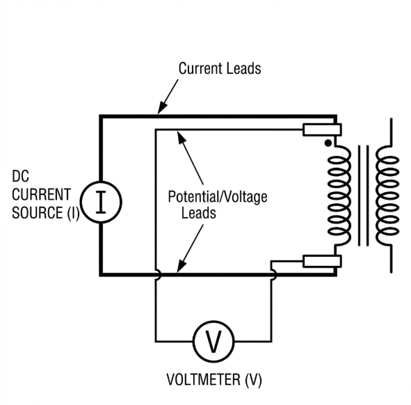
Connection diagram for performing a 4-wire Kelvin resistance measurement
3. Sweep Frequency Response Analysis (SFRA)
SFRA is the “fingerprint” of the transformer. It is the only reliable way to detect
mechanical deformation (like buckling) without opening the tank.
| Frequency Range | What It Checks | Typical Faults Detected |
|---|---|---|
| Low (20Hz – 2kHz) | Core & Inductance | Core ground issues, shorted turns, open circuits |
| Mid (2kHz – 500kHz) | Winding Interaction | Axial/Radial Deformation, movement between windings |
| High (>500kHz) | Connections & Setup | Tap changer contact issues, bushing grounding |

Example SFRA trace comparing a healthy phase (green) vs a deformed phase (red) showing frequency
shift
Short Circuit Withstand: Why Design Matters
Transformers are designed to survive short circuits for a limited time. The lower the impedance (Z%), the
higher the fault current.
IEC 60076-5 Thermal Withstand Requirements:
The standard specifies a default duration of 2 seconds for calculating thermal
short-circuit withstand, unless otherwise specified by the purchaser. The actual permissible duration
depends on factors including current magnitude and winding construction. ANSI/IEEE standards
permit up to 5 seconds for some transformer categories. Lower impedance results in higher
fault current, requiring faster protection clearing times.
If your protection relays are set too slow (e.g., clearing a fault in 3+ seconds on a low-impedance
unit), you are risking cumulative thermal damage and mechanical stress to the windings.
Repair vs. Replace: The Hard Truth
When a winding fault is confirmed, you face a tough decision.
| Scenario | Can it be repaired? | Recommendation |
|---|---|---|
| Loose connection / Tap changer contact | ✅ Yes | On-site repair often possible. Drain oil, tighten/replace contacts. |
| Minor Insulation resistance drop (wet) | ✅ Yes | Dry out process / Oil processing. |
| Inter-turn short circuit | ❌ No | Requires complete rewind. For smaller units (< 2MVA), usually cheaper to replace. |
| Winding Deformation (SFRA fail) | ❌ No | Unit is compromised. Replace reliability-critical units immediately. |
Frequently Asked Questions
Can I detect a winding fault with DGA?
Yes, often. High Acetylene (C2H2) indicates arcing (short circuit), while High Hydrogen (H2) can
indicate partial discharge in the winding. However, DGA won’t detect mechanical deformation
(buckling)
until it causes an electrical fault.
Why is low winding resistance important?
Even a small increase in resistance (due to a loose bolt) creates a “hot spot.” Heat = I²R. As heat
rises, resistance rises further, leading to thermal runaway and eventual melting of the connection.
How often should I do SFRA testing?
We recommend SFRA: 1) At the factory (baseline), 2) After shipping/delivery (to check for transport
damage), and 3) After any external fault/trip events. It’s not usually a yearly maintenance test.
Does a good Turns Ratio test prove the winding is healthy?
No. TTR only proves there are no shorted turns. It does not tell you if the winding is
loose,
deformed, or mechanically weak. You need resistance and SFRA tests for a complete picture.
What is the Kelvin Bridge method?
It is a 4-wire resistance measurement technique used to eliminate test lead resistance. Since
transformer winding resistance is very low (milliohms), standard 2-wire multimeter leads would
introduce huge errors. Kelvin probes are essential for accuracy.
Conclusion
Winding faults are complex, but they don’t have to be mysterious. By establishing a “fingerprint” with
SFRA and Resistance Testing when the unit is healthy, you can easily spot changes
later.
If you suspect a winding fault, do not re-energize the unit. The mechanical forces of a second inrush
could turn a minor fault into an explosive failure.
Send your data to our engineering team. We specialize in interpreting complex frequency response
patterns.Contact Us for Analysis