
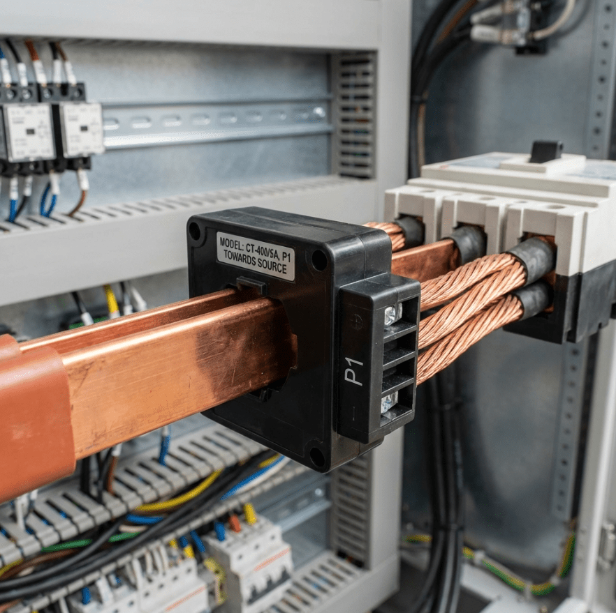
In my 15 years working with power systems at Transformer4U, I’ve seen more protection relays trip due to
CT wiring errors than actual grid faults. Connecting a Current Transformer (CT) isn’t just
about matching wires; it’s a critical safety procedure where a single mistake can be lethal.
💡 Quick Answer: To connect a Current Transformer correctly:
- Mounting: Ensure the primary side marked P1 (or H1)
faces the Power Source.- Wiring: Connect secondary logic: S1 → Meter(+) and S2 →
Meter(-).- Grounding: Always ground the S2 terminal at one point to prevent
static buildup.- Safety: NEVER open-circuit the secondary while energized!
Whether you are dealing with IEC standard (P1/P2) or IEEE standard (H1/H2) transformers, this guide covers the
exact protocols we use in our factory to ensure safety and accuracy.
1. Safety First: The Golden Rule (Experience from the Field)
Before we touch any screwdriver, I must emphasize the most important rule in our industry. I once witnessed a
junior technician almost make this fatal mistake during a commissioning test.

⚠️ CRITICAL WARNING: Never Open-Circuit a CT Secondary!
Unlike voltage transformers, a current transformer must never be operated with its secondary
circuit open while the primary is energized.
Why? An open secondary forces the CT to act as a step-up transformer with infinite burden.
This causes the magnetic core to fully saturate, inducing dangerously high peak voltages
(often kilovolts) across the open terminals. This can instantly destroy the insulation and cause a lethal
arc flash.
Our Factory Protocol: We always use a shorting terminal block.
Before disconnecting any meter, we insert the shorting link first.
2. Understanding CT Terminal Markings (Polarity)
The most common installation error we troubleshoot is reversed polarity. If you flip the
connection, your power meter will read negative kW, and your differential protection relay will trip instantly
upon energization.
Depending on where your equipment was manufactured, you will see different markings. Here is the comparison table
I use to train our new engineers:
IEC vs. IEEE Standard Markings Calculation
| Feature | IEC 61869 (Europe/Asia) | IEEE C57.13 (North America) |
|---|---|---|
| Primary Terminals | P1, P2 (or K, L) | H1, H2 |
| Secondary Terminals | S1, S2 (or k, l) | X1, X2 |
| Flow Direction | Current enters P1 → Exits P2 | Current enters H1 → Exits H2 |
| Polarity Match | S1 is positive when P1 is positive | X1 is positive when H1 is positive |
For more deep dives into standards, you can refer to the IEC 61869 Standard or IEEE C57.13
guidelines.
Physical Orientation
Keep this simple rule in mind: “Source to Load”.
- P1 / H1 (Primary Start) must always face the **SOURCE** (Grid/Supply).
- P2 / H2 (Primary Finish) must always face the **LOAD** (Consumer).
3. Step-by-Step Wiring Guide
A. Single Phase CT Connection (2-Wire)

This is standard for ammeters. In our single-phase
transformers:
- Primary: Pass the main live phase cable through the CT window (Source entering P1 side).
- Secondary:
- Connect wire from S1 (k) to the Meter Current Input (+) or k.
- Connect wire from S2 (l) to the Meter Current Input (-) or l.
- Grounding:
Always ground one side of the CT secondary (typically S2).
This prevents the secondary circuit from floating to a high potential if the primary insulation fails.
B. Three Phase Star Connection (Residual)
For our three-phase systems, we typically use
the Star (Wye) connection:
- Connect S1 of Phase A, B, and C CTs to their respective meter inputs.
- Link all three S2 terminals together. This creates a “Star Point”.
- Run a single common return wire from the Star Point to the meter neutral.
- Ground the Star Point securely at the CT terminal box.
4. Pre-Energization Checklist
Before throwing the switch, I always run through this personal checklist:
- ✅
Orientation: Is P1/H1 facing the source? - ✅ Tightness:
Are secondary screws tight? (Loose connections = Heat = Overheating). - ✅ Wire
Gauge: Is the wire thick enough (2.5mm²+) to minimize burden? High burden leads to CT Saturation. - ✅ Grounding:
Is S2 grounded at ONLY one point? (Avoid ground loops). - ✅ Burden
Check: Is the load within the CT’s VA rating? Use our Burden Calculator to verify.
5. Troubleshooting: The 9V Battery Trick
Sometimes the labels on old CTs rub off. In the field, we use a simple “Kick Test” to determine polarity using a
multimeter and a 9V battery.
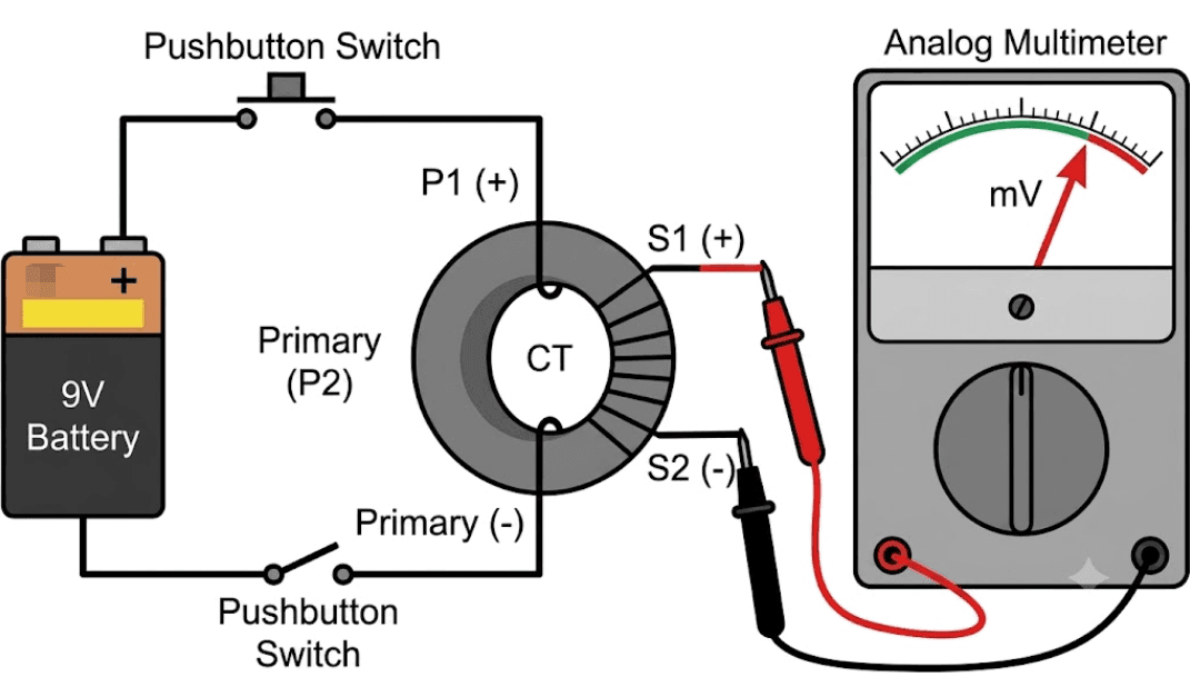
- Connect an analog voltmeter (DC mV range) to secondary (guess S1 = +, S2 = -).
- Briefly touch a 9V battery to the primary (Positive to P1 side, Negative to P2 side).
- Watch the needle:
- Kick Right (Positive): Your S1 assumption is correct. Polarity is standard.
- Kick Left (Negative): Your connections are reversed. S1 is actually S2.
Need help with specific wiring diagrams? Whether it’s for protection or metering, achieving the
correct CT Ratio and connection is vital.
Contact us at Transformer4U for expert support.