
Written by Tan, Electrical Engineer @ Transformer4U · Updated May 2026
Choosing the wrong CT size is one of the most common — and costly — mistakes in electrical installations. I’ve seen a warehouse retrofit where someone installed 2000:5 CTs on circuits carrying only 150A. The meters read near-zero, and the facility lost 14 months of energy data before anyone noticed.
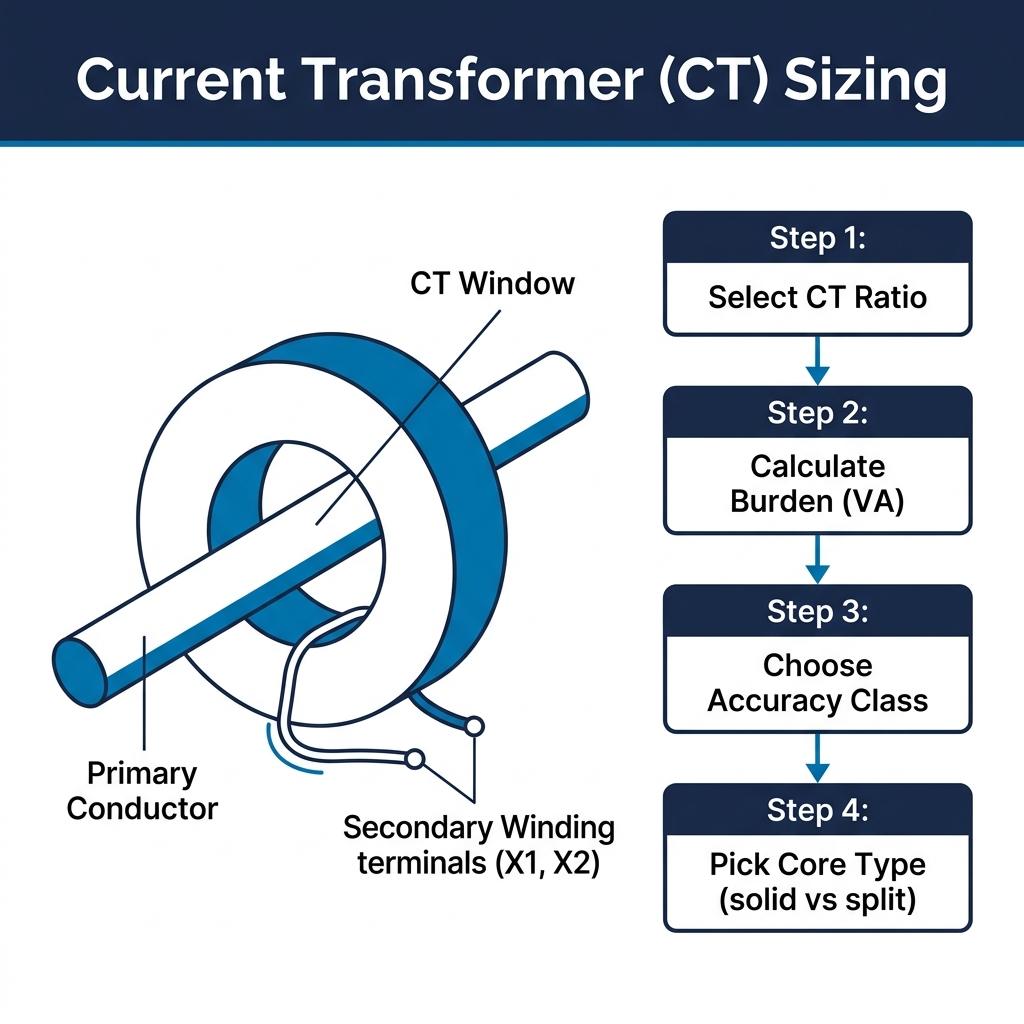
CT sizing comes down to four decisions: ratio, burden, accuracy class, and core type. Get these right and your metering or protection system will perform reliably for decades.
Step 1: Select the CT Ratio
The CT ratio determines how primary current maps to secondary current (typically 5A or 1A). The rule is simple: pick a primary rating slightly above your maximum expected current.
| Circuit Current (A) | Recommended CT Ratio | Secondary at Full Load |
|---|---|---|
| 75–100 | 100:5 | 3.75–5.0 A |
| 150–200 | 200:5 | 3.75–5.0 A |
| 300–400 | 400:5 | 3.75–5.0 A |
| 600–800 | 800:5 | 3.75–5.0 A |
| 1000–1200 | 1200:5 | 4.17–5.0 A |
For a deeper look at all standard ratios from 50A to 6000A, see our CT Ratio Chart.
⚠️ Avoid oversizing. A CT operating below 25% of its rated primary current will show significantly higher percentage errors, degrading both metering accuracy and power factor readings.
Step 2: Calculate the Total Burden
Burden is the total impedance load on the CT secondary — including wire resistance and connected instruments. The CT’s rated VA must exceed the total burden; otherwise, accuracy drops sharply.
Total Burden (VA) = I²s × (Rwire + Rmeter)
Example: CT secondary = 5A, wire run = 15m (both ways = 30m) using 2.5mm² copper (≈ 7.4 Ω/km):
Rwire = 0.03 km × 7.4 = 0.222 Ω
Rmeter = 0.02 Ω
Total Burden = 25 × 0.242 = 6.05 VA → Select a CT rated ≥ 10 VA.
Tip from the field: For long wire runs (>15m), consider using 1A secondary CTs instead of 5A. The burden drops by 25× (since burden is proportional to I²), as recommended by IEC 61869-2.
CT VA Rating vs. Maximum Wire Length
Use this table to select the minimum CT VA rating for your installation. Assumes 5A secondary, 2.5 mm² copper wire, 0.02 Ω meter resistance at 20°C. For 1A secondary CTs, multiply all distances by 25.
| CT VA Rating | Max Wire Run — 5A Secondary | Max Wire Run — 1A Secondary | Typical Application |
|---|---|---|---|
| 2.5 VA | ~5 m (16 ft) | ~125 m (410 ft) | Panel-mounted meter, very short run |
| 5 VA | ~12 m (40 ft) | ~300 m (985 ft) | Local subpanel metering |
| 10 VA | ~25 m (82 ft) | ~625 m (2050 ft) | Most commercial installations |
| 15 VA | ~39 m (128 ft) | ~975 m | Remote metering rooms |
| 30 VA | ~80 m (262 ft) | ~2000 m | Substation to control room runs |
Wire resistance calculated at 7.41 Ω/km for 2.5 mm² copper (IEC 60228). Total run = 2× one-way distance.
Step 3: Choose the Right Accuracy Class
| Application | ANSI/IEEE Class | IEC Class | Max Error |
|---|---|---|---|
| Revenue billing | 0.3 | 0.2 / 0.5 | 0.3% |
| General monitoring | 0.6 / 1.2 | 1.0 | 0.6–1.2% |
| Overcurrent protection | C200 | 5P20 | 5% at 20× rated |
| Differential protection | C400 / C800 | PX (PS class) | Per knee point spec |
Protection CTs must handle short circuit currents without saturating. Per IEEE C57.13, the CT’s rated short-time thermal current (Ith) must exceed the prospective fault level at the installation point.
Step 4: Pick Solid Core or Split Core
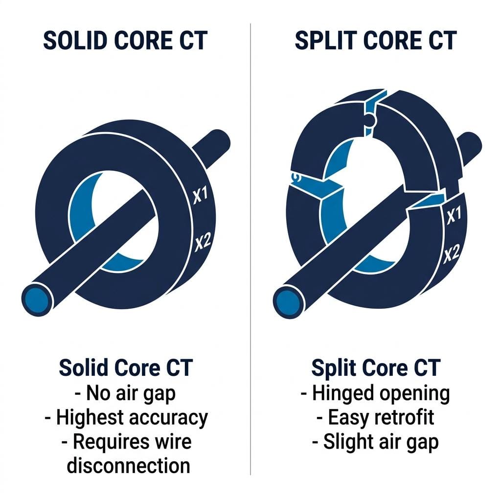
| Feature | Solid Core CT | Split Core CT |
|---|---|---|
| Installation | Requires circuit disconnection | Clamps around live cable |
| Accuracy | Highest (no air gap) | Slightly lower (joint air gap) |
| Cost | Lower | Higher |
| Best for | New installations, revenue metering | Retrofits, energy audits |
Sizing the window: The CT’s inner diameter must fit around the conductor. For best accuracy, the conductor should fill at least 50% of the CT window opening. A #4/0 AWG cable (≈16mm bare conductor diameter) fits well in a 25mm window CT, but would be dwarfed in a 50mm window — and accuracy would suffer.
CT Window Size vs. Conductor Size (AWG / kcmil)
Select a CT whose window is large enough to fit the cable, but no more than twice the cable’s outer diameter for best accuracy.
| Wire Size | Typical OD (THHN) | Typical Ampacity (75°C) | Min CT Window | Max CT Window (2× rule) |
|---|---|---|---|---|
| #10 AWG | ~5.3 mm (0.21 in) | 35 A | 16 mm | 20 mm |
| #8 AWG | ~6.4 mm (0.25 in) | 50 A | 16 mm | 20 mm |
| #6 AWG | ~7.7 mm (0.30 in) | 65 A | 20 mm | 25 mm |
| #4 AWG | ~9.0 mm (0.35 in) | 85 A | 20 mm | 25 mm |
| #2 AWG | ~11.2 mm (0.44 in) | 115 A | 25 mm | 32 mm |
| #1/0 AWG | ~14.0 mm (0.55 in) | 150 A | 25 mm | 32 mm |
| #2/0 AWG | ~15.6 mm (0.61 in) | 175 A | 32 mm | 40 mm |
| #3/0 AWG | ~17.5 mm (0.69 in) | 200 A | 32 mm | 40 mm |
| #4/0 AWG | ~19.8 mm (0.78 in) | 230 A | 32 mm (1.25 in) | 50 mm |
| 250 kcmil | ~23 mm (0.91 in) | 255 A | 40 mm | 50 mm |
| 350 kcmil | ~26 mm (1.02 in) | 310 A | 50 mm | 60 mm |
| 500 kcmil | ~30 mm (1.18 in) | 380 A | 60 mm | 80 mm |
OD values for THHN/THWN-2 insulation per NEC Chapter 9, Table 5. Ampacity at 75°C per NEC 310.16. “2× rule”: conductor OD should be >50% of CT window for best accuracy (per CCS/ctlsys).
From the factory floor: When I install a solid core CT, I always check that it slides snugly over the bus bar — you should feel a slight resistance as the conductor fills the window. If the CT wobbles loosely, it’s oversized and you’ll see noisy readings on the meter. A properly sized CT sits firm and centered, and the secondary terminal screws should torque down cleanly at 1.5 N·m.
Common CT Sizing Mistakes to Avoid
- Oversizing the ratio: An 800:5 CT on a 120A circuit gives only 0.75A secondary — below most meter accuracy thresholds.
- Ignoring wire burden: A 50-foot (15m) wire run with thin cable can consume most of a CT’s rated VA, pushing it out of its accuracy class.
- Using metering CTs for protection: Metering CTs saturate early to protect instruments. During a fault, the relay sees a clipped waveform and may fail to trip. Always use separate protection cores.
- Forgetting future load growth: Size for projected maximum current, not today’s load. A 25% growth margin is standard practice.
Frequently Asked Questions
How do I determine the correct CT ratio?
Select a CT with a primary rating 10–25% above your maximum expected load current. For example, if your circuit carries 350A, choose a 400:5 CT. Avoid oversizing — an 800:5 CT on a 200A circuit produces only 1.25A secondary, which degrades metering accuracy.
What is the difference between solid core and split core CTs?
A solid core CT is a closed ring offering highest accuracy but requires disconnecting the conductor for installation. A split core CT has a hinged design that clamps around a live cable, making it ideal for retrofits. Split core CTs have slightly lower accuracy due to air gaps at the joint.
How does short circuit current affect CT sizing?
Protection CTs must remain unsaturated during short circuit events. The CT must withstand the thermal and dynamic effects of fault current for at least 1 second. Choose a CT with a short-time thermal current rating (Ith) that exceeds the prospective fault current at the installation point.
What CT accuracy class should I use?
For revenue metering, use Class 0.3 (ANSI) or Class 0.5 (IEC). For general monitoring, Class 0.6 or 1.0 is sufficient. For protection relaying, use C200 or 5P20 class CTs that maintain linearity at high fault multiples.
Can I use one CT for both metering and protection?
No. Metering CTs saturate early to protect instruments from fault currents, while protection CTs stay linear at 20× rated current. Using one for both compromises either billing accuracy or relay reliability. Use separate cores for each function.
Related Articles