
helped hundreds of engineers navigate this decision.In this guide, I’ll break down every major type of transformer, share selection
insights from the factory floor, and help you avoid costly mistakes.
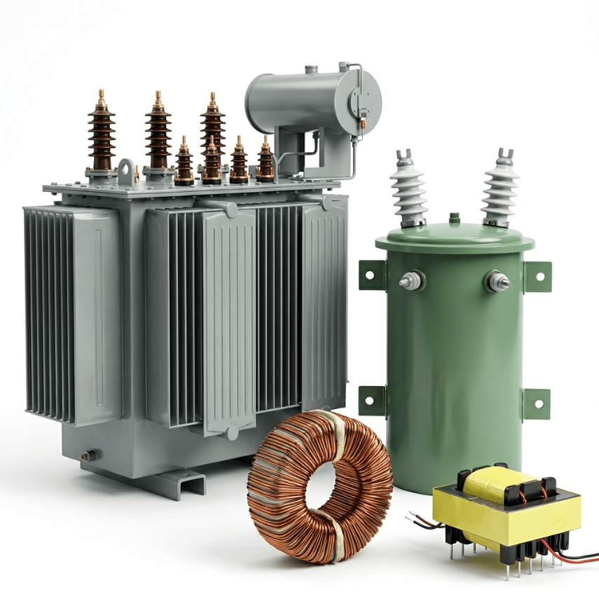
Quick Answer: The main types of transformer include:
- By Voltage: Step-Up, Step-Down, Isolation
- By Application: Power, Distribution, Instrument (CT/PT)
- By Core: Iron Core, Ferrite Core, Air Core, Toroidal
- By Phase: Single-Phase, Three-Phase
- By Winding: Two-Winding, Auto-Winding
7 Ways to Classify Types of Transformer
Before diving into specific types, let’s understand why these classifications matter.
Transformers can be categorized by multiple criteria, and the right choice depends
entirely on your application.
| Classification Basis | Types |
|---|---|
| By Voltage Level | Step-Up, Step-Down, Isolation |
| By Application | Power, Distribution, Instrument |
| By Core Design | Core Type, Shell Type, Iron, Ferrite, Air, Toroidal |
| By Supply Phase | Single-Phase, Three-Phase |
| By Winding Arrangement | Two-Winding, Auto-Winding |
Why Understanding Types Matters
Choosing the wrong transformer type can lead to serious problems:
- Efficiency losses — wasting electricity means wasting money
- Overheating — undersized transformers fail prematurely
- Safety hazards — using autotransformers where isolation is required can be
dangerous - System incompatibility — mismatched vector groups cause circulating currents
Types of Transformer by Voltage Level
The most fundamental classification is based on what the transformer does to voltage: increase it,
decrease it, or keep it the same.
Step-Up Transformer
A step-up transformer increases voltage from the primary side to the
secondary coil. This happens when the secondary winding has more turns than the
primary.
Key Formula:
V₂/V₁ = N₂/N₁ > 1
Where N₂ (secondary turns) > N₁ (primary turns), resulting in higher voltages on the
output.
Common Applications:
- Power generation stations (11kV → 132kV for transmission)
- Solar inverter systems
- Voltage boosters for industrial equipment
In our factory, we produce step-up transformers for solar inverter systems. A typical unit converts 48V
AC power (from an inverter) to 230V for home use. The efficiency of these units
typically exceeds 95%.
Step-Down Transformer
A step down transformer does the opposite — it reduces secondary
voltage
to a lower level. The primary and secondary windings are designed so that N₁ > N₂.
Key Formula:
V₂/V₁ = N₂/N₁ < 1
Common Applications:
- Distribution networks (11kV → 400V/230V)
- Power adapters and chargers
- Industrial control systems
- Electronic devices
Most transformers you encounter daily are step-down types. The transformer on your street steps down
voltage from the distribution grid to a level safe for your home.
→ Learn more: Power Transformer: Ultimate
Guide
Isolation Transformer
An isolating transformer maintains the same voltage level (1:1 turns ratio) while
providing electrical isolation between primary and secondary coils. No direct
electrical connection exists between the two sides — only magnetic coupling.
Why Use Isolation?
- Protect sensitive equipment from power line noise
- Prevent ground loops in audio systems
- Provide safety isolation in medical environments
- Eliminate common-mode interference
Real-World Example: In hospitals, medical-grade isolation transformers
protect life-support equipment from power line disturbances. A single voltage spike could interfere with
a patient monitor — isolation transformers prevent this by completely separating the equipment from the
main power grid. This is why medical isolation transformers must meet strict
IEC 60601 safety standards.
Comparison Table
| Feature | Step-Up | Step-Down | Isolation |
|---|---|---|---|
| Turns Ratio (N₂/N₁) | > 1 | < 1 | = 1 |
| Output Voltage | Higher | Lower | Same |
| Primary Use | Transmission | Distribution | Safety/Isolation |
| Example | 11kV → 132kV | 11kV → 400V | 230V → 230V Medical |
Types of Transformer by Application
Different applications require transformers with specific characteristics. Here’s how the industry
classifies them.
Power Transformer
Power transformers are the giants of the electrical grid. They handle high
voltage transmission, typically rated at 33kV to 400kV with capacities exceeding 200MVA.
Characteristics:
- Designed for maximum efficiency at full load (near 100%)
- Oil-immersed for cooling (ONAN, ONAF, OFAF)
- Installed at generating stations and transmission substations
- Operate continuously at stable loads
When I visit partner substations for installation support, the first thing I check is the nameplate.
Here’s what a typical distribution-class power transformer nameplate shows:
| Parameter | Example Value |
|---|---|
| Rated Power | 1,000 kVA (1 MVA) |
| Primary Voltage | 11,000 V |
| Secondary Voltage | 400 V |
| Vector Group | Dyn11 |
| Impedance | 5% |
| Cooling | ONAN |
The impedance percentage (5%) is important — it limits short-circuit currents, protecting the transformer
and connected equipment. Higher impedance means better fault protection but slightly lower voltage
regulation.
Distribution Transformer
Distribution transformers are what most people picture when they think of transformers.
They’re everywhere — on poles, in underground vaults, and inside pad-mounted enclosures.
Characteristics:
- Lower power ratings: typically 16kVA to 2,500kVA
- Voltage levels: 11kV, 6.6kV, 3.3kV down to 400V/230V
- Designed for “all-day efficiency” (60-70%), accounting for variable loads
- Types: Pole-mounted, Pad-mounted, Underground/Submersible
Distribution transformers experience significant load variations throughout the day. They’re lightly
loaded at night and heavily loaded during peak hours. That’s why they’re optimized for all-day
efficiency rather than maximum load efficiency.
Instrument Transformer (CT & PT)
Instrument transformers don’t power loads — they measure electric power safely. High
voltages and currents can’t be measured directly, so we step them down to safe, manageable levels.
Current Transformer (CT):
- Connected in series with the primary to secondary circuit
- Steps down current (e.g., 2000A → 5A)
- Typical ratio: 2000:5, 1000:1, etc.
- Used for metering and protection relays
Potential Transformer (PT):
- Connected in parallel
- Steps down voltage (e.g., 11kV → 110V)
- Typical ratio: 11000:110, 500:120
→ Learn more: Current
Transformer Complete Guide
Types of Transformer by Core Design
The magnetic core is the heart of any transformer. Its construction, material, and
shape significantly impact performance.
Core Construction
Core Type: In a core-type transformer, the primary and secondary
windings are wound around two separate limbs of a rectangular core. This design offers
better cooling (windings exposed), is preferred for high-voltage applications
(typically up to 132kV and above), and is easier to repair.
Shell Type: In a shell-type transformer, the core surrounds the windings. This design
provides better mechanical protection, lower leakage inductance, and is preferred for
low-voltage, high-current applications (typically below 33kV).

Core Material
| Material | Characteristics | Best For |
|---|---|---|
| Laminated Iron | High permeability, low-frequency (50/60Hz) | Power & Distribution |
| Ferrite Core | Low loss at high frequency (50kHz–500kHz) | SMPS, Chargers, RF |
| Air Core | No core, high leakage inductance, no saturation | RF, Wireless Charging |
An air core transformer uses no physical core — magnetic coupling happens through air.
This eliminates core losses entirely but results in very low mutual inductance. They’re essential for
high-frequency radio applications where ferrite would saturate.
Ferrite core transformers dominate in switch-mode power supplies (SMPS). The ferrite
material maintains low losses even at typical switching frequencies of 50kHz–500kHz, enabling compact,
efficient power adapters like your phone charger.
Core Shape
EI / Solenoidal Core: Traditional rectangular cores made from E-shaped and I-shaped
laminations. Cost-effective and suitable for multi-phase designs.
Toroidal Core: Toroidal core transformers use a donut-shaped core,
offering significant advantages: significantly reduced stray magnetic fields (up to 10× lower than EI
cores), higher efficiency, compact design, and lower audible noise.
Toroidal transformers are my personal favorite. When you lift one, you’ll immediately notice how compact
and balanced the weight is compared to an EI transformer of the same rating.
Types of Transformer by Phase
Single-Phase Transformer
Single-phase transformers work with single-phase AC power supplies. They’re common in
residential applications, light commercial use, electronic equipment, and control circuits. Typical
ratings range from a few VA to 5 MVA.
Three-Phase Transformer
Three-phase transformers handle three-phase power, essential for industrial applications and
power distribution networks. The three phases are 120° apart electrically.
| Primary | Secondary | Symbol | Phase Shift |
|---|---|---|---|
| Star (Y) | Star (Y) | Yy0 | 0° |
| Delta (Δ) | Delta (Δ) | Dd0 | 0° |
| Delta (Δ) | Star (Y) | Dyn11 | 30° lag |
| Star (Y) | Delta (Δ) | YNd1 | 30° lead |
Understanding Vector Groups (The “Clock” Notation):
The notation “Dyn11” means: D = Delta-connected primary,
y
= Star-connected secondary, n = Neutral available, 11 = Phase shift as
a clock position.
The number uses a clock face analogy: if the primary voltage is at 12 o’clock, the secondary voltage
points to the 11 o’clock position — a 30° phase lead. Each “hour” represents 30°, so “11” means 11 × 30°
= 330° (or equivalently, 30° leading).
This standardized notation helps engineers quickly identify compatibility when paralleling
transformers — mismatched vector groups cause circulating currents that can damage
windings.
Special Types of Transformer Explained
Autotransformer
An autotransformer uses a single winding for both primary and secondary, with a portion shared. This
offers smaller size, lower cost, and higher efficiency.
secondary. Never use them where isolation is required — such as medical equipment, bathroom outlets, or
outdoor installations where ground faults could cause electrocution.
Applications:
- VARIAC (variable autotransformer) for laboratory testing
- Motor starters (reduced voltage starting)
- Voltage adjustment within ±20%
Pulse Transformer
Pulse transformers are optimized for transmitting rectangular electrical pulses with minimal distortion.
They’re used in digital communication circuits, Ethernet interfaces, and gate drive circuits for power
electronics.
Audio Transformer
Audio transformers match impedance between amplifiers and speakers, or between microphones and preamps.
Key requirements include flat frequency response across the audible range (20Hz–20kHz) and low
distortion.
Which Type of Transformer Do I Need?
Here’s a quick selection guide based on common requirements:
| Your Requirement | Recommended Type |
|---|---|
| High-voltage power transmission | Power Transformer (Step-Up) |
| Supply homes and businesses | Distribution Transformer (Step-Down) |
| Measure high current safely | Current Transformer (CT) |
| Measure high voltage safely | Potential Transformer (PT) |
| Audio impedance matching | Audio Transformer |
| Compact switching power supply | Ferrite Core Transformer |
| Low noise, audio equipment | Toroidal Core Transformer |
| Variable voltage output | Autotransformer (VARIAC) |
| Electrical isolation required | Isolating Transformer |
Our engineering team can help you select the right transformer for your specific application.
Get a Free Consultation →
5 Common Selection Mistakes to Avoid
Based on years of helping customers, here are the most frequent errors:
- Choosing based on price alone — Cheap transformers often have poor efficiency,
costing more in electricity over their lifetime. - Undersizing the transformer — A transformer running at 110% load will overheat and
fail prematurely. Always include a 20-30% safety margin. - Using autotransformer where isolation is needed — This is a safety hazard. If in
doubt, choose an isolation transformer. - Ignoring ambient temperature — A transformer rated for 40°C ambient will derate in
hotter environments. Check the derating curve. - Mismatching vector groups — When paralleling transformers, vector groups
must match, or circulating currents will damage the units. - Ignoring harmonic loads — If you’re powering VFDs, LED lighting, or computers,
consider a K-rated transformer designed for non-linear loads.
Frequently Asked Questions
By voltage function, the three main types of transformer are:
Step-Up
(increases voltage), Step-Down (decreases voltage), and
Isolation (maintains voltage while providing electrical separation).
Power transformers (>200MVA) are designed for high-voltage transmission at
generating stations. Distribution transformers (<200MVA) step down voltage to
consumer levels (230V/400V) and are found on poles and in substations throughout
neighborhoods.
Homes receive power through distribution transformers — either pole-mounted or
pad-mounted units that step down voltage from the distribution grid (11kV) to household levels
(230V/400V).
No. Transformers rely on changing magnetic flux, which only alternating current (AC) produces. A
steady DC current creates a constant magnetic field with no flux change, so no voltage is
induced in the secondary.
Distribution transformers are by far the most common. Every neighborhood,
commercial building, and industrial facility requires them to receive usable power from the
grid.
Transformer humming is caused by magnetostriction — the slight expansion and contraction of the
iron core as the magnetic field alternates at 50/60Hz. Low-level humming is normal. Loud or
changing hum may indicate loose laminations, overloading, or DC offset in the supply.
A well-maintained oil-filled transformer typically lasts 25-40 years.
Dry-type transformers may last 15-25 years. Lifespan depends heavily on
operating temperature, loading conditions, and maintenance practices.
Key Takeaways
- Voltage-based classification (Step-Up, Step-Down, Isolation) determines how
voltage is transformed - Application-based classification (Power, Distribution, Instrument) matches
transformers to their role in the grid - Core design (material and shape) affects efficiency, size, and frequency range
- Toroidal and ferrite core transformers excel in electronics
and high-frequency applications - Always choose isolation transformers when safety separation is required
- Avoid autotransformers where electrical isolation is necessary
Need a Custom Transformer Solution?
Whether you need a toroidal core transformer for audio equipment or a distribution
transformer for your facility, our engineering team at Transformer4U can help.
References