

In my 15 years as a technician at Transformer4U, I’ve noticed a pattern: 90% of the confusion in three-phase power comes from the Delta
connection. Unlike the Wye (Star) connection with its comforting neutral point, the Delta
connection can feel like a “floating” mystery loop.
I remember one specific night shift where a customer called about their manufacturing plant’s motors overheating.
They swore their voltage was 240V balanced. When I drove out there, I found they had miswired a **High-Leg
Delta** system, feeding 208V into a 120V automatic control circuit. That “wild leg” cooked their PLC board
instantly.
This guide isn’t just about textbook diagrams. It’s about helping you visualize, wire, and troubleshoot Delta
transformers safely.
💡 Quick Answer:
A Delta Transformer Diagram connects three windings end-to-end to form a closed loop
(Triangle).
- Voltage Rule: Line Voltage = Phase Voltage ($V_{L} = V_{P}$).
- Current Rule: Line Current = $\sqrt{3} \times$ Phase Current ($I_{L} = 1.732 \times
I_{P}$).- Key Feature: No neutral required for 3-wire power; ideal for heavy motor loads and
maintaining power during a single-phase fault (Open-Delta).
1. What is a Delta Connection? (The “Mesh”)
Imagine holding three ropes tied in a circle. That’s a Delta. In a Delta (Δ) configuration, the
end of one winding is connected to the start of the next winding:
- Winding A: Finish connects to B Start.
- Winding B: Finish connects to C Start.
- Winding C: Finish connects to A Start.
The Voltage & Current Rule
This is the most critical formula we use on the manufacturing floor:
| Parameter | Delta Connection (Δ) | Wye Connection (Y) |
|---|---|---|
| Voltage | $V_{Line} = V_{Phase}$ (Windings see full Grid Voltage) | $V_{Line} = \sqrt{3} \times V_{Phase}$ |
| Current | $I_{Line} = \sqrt{3} \times I_{Phase}$ | $I_{Line} = I_{Phase}$ |
| Neutral | No Neutral (unless center-tapped) | Native Neutral Point |
Expert Insight: Because the windings see the full Line-to-Line voltage, Delta windings require
more insulation than Wye windings for the same voltage class. This is why we often prefer Wye
on the High Voltage (HV) side of massive grid transformers.
2. Standard Delta Transformer Diagrams
A. Delta-Delta (Dd) – “The Industrial Workhorse”
We see this mostly in older manufacturing plants. Ideally suited for motor connections.
- Pros: It has a superpower called the “Open Delta”. If one of the three
single-phase transformers fails, you can physically remove it, and the remaining two will still
provide 58% of the power. I’ve used this trick to keep a sawmill running while waiting for a replacement
unit. - Cons: No stable neutral reference. If a ground fault occurs, the ungrounded system voltage
can float dangerously high.
B. Delta-Wye (Dy) – “The Distribution King”
This is almost certainly what is powering your building right now.
- Pros: The Delta primary “traps” 3rd harmonic currents, keeping the utility grid clean. The
Wye secondary gives you two voltages: e.g., 480V for motors (Phase-to-Phase) and
277V for lights (Phase-to-Neutral). - Phase Shift: Note that standardized Delta-Wye transformers create a 30° Phase
Shift (typically Dyn1 or Dyn11 vector
groups).
3. The “High-Leg” Delta (Red-Leg / Wild-Leg)
⚠️ DANGER ZONE: The 208V Trap
A 4-Wire Delta system is a standard Delta secondary, but one winding is
center-tapped and grounded. This creates a “High Leg” on Phase B.
- Phase A to Neutral: 120V
- Phase C to Neutral: 120V
- Phase B to Neutral: $120 \times \sqrt{3} = 208V$ (The High Leg!)
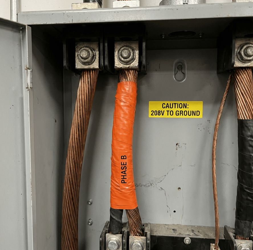
Real World Warning: I once inspected a panel where an apprentice wired a single-phase breaker to
the “B” phase because it was “just an empty slot”. He fed 208V into a row of 120V computers. Always
measure voltage to ground before adding a breaker to a Delta panel.
4. Troubleshooting Delta Connections
In our factory testing bay (Tan’s Lab), we follow these steps when a Delta transformer acts up:
Step 1: Check for “Circulating Current”
In a closed Delta loop, if the voltage ratios of the three windings aren’t exactly the same, a massive
current will flow inside the loop even with no load connected.
- Test: Open one corner of the Delta. Connect a Voltmeter across the open gap.
- Result: It should read 0V. If you see significant voltage (e.g., >5% of
rated V), you have a ratio mismatch or a shorted turn. Do not close the loop!
Step 2: The Ground Detector
Since ungrounded Delta systems don’t trip breakers on the first ground fault, we install “Ground Detector
Lights”. If Phase A grounds, Light A goes dark, and Lights B & C get super bright.
Need a Custom Diagram? Designing a complex industrial power system? Don’t guess. Contact our engineering team at Transformer4U for expert advice.
For further reading:
- IEEE C57.12.00 Standard (External
Authority) - 3-Phase Transformer Connections (Electronics Tutorials)
- Review our guide on Transformer Polarity Markings.