
📑 Table of Contents
facing electrical engineers and maintenance personnel. Beyond the immediate operational concerns,
oil leaks can escalate into environmental violations, safety hazards, and costly unplanned
outages.
maintenance incidents. More critically, unaddressed leaks can reduce transformer life
expectancy by 30-50% due to moisture ingress and insulation degradation.
This guide provides a systematic approach to identifying, repairing, and preventing transformer oil
leaks based on field-proven techniques and current industry standards including IEEE
C57.93 (Guide for Installation and Maintenance of Liquid-Immersed Power Transformers).
Why Transformer Oil Leaks Are Critical
Transformer oil (also known as insulating oil) serves multiple critical functions that make any leak
a serious concern:
Primary Functions of Transformer Oil
- Electrical Insulation: Provides dielectric strength ≥30 kV (ASTM D877 minimum
for acceptable oil) between
windings and tank - Heat Transfer: Removes heat from windings through convection to external
radiators - Arc Suppression: Quenches internal arcs and prevents corona discharge
- Moisture Barrier: Protects cellulose insulation from atmospheric moisture
Consequences of Unaddressed Leaks
| Impact Area | Consequence | Severity |
|---|---|---|
| Oil Level Drop | Exposed windings, reduced cooling capacity | Critical |
| Moisture Ingress | Dielectric strength reduced by 50% at 30ppm water | High |
| Insulation Aging | Paper insulation life reduced exponentially | High |
| Environmental | Soil/water contamination, regulatory fines | High |
| Fire Risk | Oil pooling near heat sources (flash point >140°C) | Critical |
investigated, moisture content had risen from 8ppm to 45ppm, and DGA showed elevated hydrogen
indicating early thermal degradation. What could have been a $500 gasket replacement became a
$50,000 oil reconditioning and monitoring program.
Common Causes of Transformer Oil Leaks
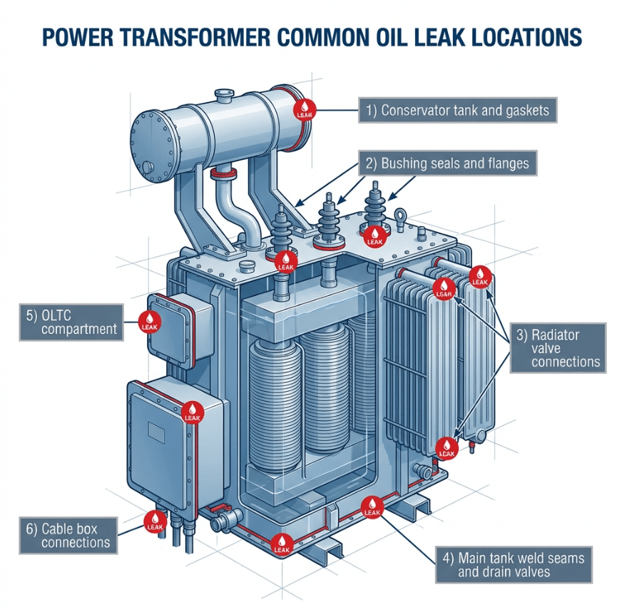
Diagram showing common oil leak locations on a power transformer
1. Gasket Deterioration (60-70% of leaks)
Gaskets are the most common source of transformer oil leaks. They deteriorate due to:
- Age: Nitrile rubber gaskets typically last 5-10 years in service (up to 15-20
years without heat cycling) - Heat cycling: Repeated expansion/contraction causes compression set
- UV degradation: External gaskets exposed to sunlight
- Chemical attack: Incompatible oils or additives
- Over-torquing: Excessive bolt tightening during installation
esters, and synthetic esters have different compatibility requirements. Check with the gasket
manufacturer for oil compatibility charts.
2. Weld Cracks and Tank Defects
Structural issues in the tank or radiators include:
- Thermal stress cracks: From rapid temperature changes
- Manufacturing defects: Incomplete weld penetration
- Corrosion: Tank wall thinning, especially in humid environments
- Vibration fatigue: At radiator connections and support brackets
3. Bushing Seal Failures
Bushing-to-tank seals are critical leak points:
- O-ring degradation from heat and age
- Flange gasket compression loss
- Bushing mounting hardware loosening
- Thermal expansion mismatches between bushing and tank materials
4. Valves and Fittings
| Component | Common Leak Cause | Solution |
|---|---|---|
| Drain Valve | Stem packing wear, seat damage | Repack or replace valve |
| Sample Valve | Improper closure after sampling | Train personnel, install caps |
| Radiator Valves | Gasket degradation, thermal cycling | Replace gaskets, check torque |
| Pressure Relief | Diaphragm failure, seat erosion | Replace device |
5. Conservator and Breather System
- Air cell/bladder punctures or aging
- Conservator tank gasket failures
- Breather connection leaks
- MOG (Magnetic Oil Gauge) mounting gaskets
6. Physical Damage
- Impact damage from equipment or vehicles
- Vandalism
- Severe weather (falling debris)
- Seismic events
Detection Methods & Monitoring
Daily Visual Inspection
The most effective leak detection remains routine visual inspection. Train personnel to look for:
- Oil stains or drips on tank surfaces
- Wet spots on gravel or concrete pads
- Discoloration on radiators and fittings
- Oil accumulation in transformer bund/containment
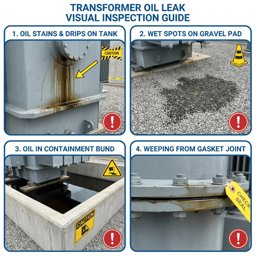
Visual indicators of transformer oil leaks
Oil Level Monitoring
Magnetic Oil Gauge (MOG)
The MOG is the primary oil level indicator for power transformers. It consists of:
- Float inside conservator tank connected to bevel gear
- Magnetic coupling to external dial indicator
- Mercury switch for low-oil alarm activation
temperature rise can cause noticeable oil expansion. If the oil level drops unexpectedly without
temperature change, investigate immediately.
Electronic Oil Level Sensors
Modern transformers may include:
- Float switches with alarm contacts
- Capacitive level sensors
- Ultrasonic level measurement
- Integration with SCADA systems for remote monitoring
Advanced Detection Techniques
| Method | Application | Sensitivity |
|---|---|---|
| Infrared Thermography | Identify cold spots from evaporative cooling | Medium |
| UV Fluorescent Dye | Pinpoint small/slow leaks | High |
| Pressure Decay Test | Verify tank integrity during maintenance | High |
| Oil Consumption Tracking | Detect gradual losses over time | Medium |
UV light after 24-48 hours of operation. The dye will highlight leak paths that are invisible under
normal lighting.
Leak Location Identification
Systematic inspection helps identify leak sources efficiently:
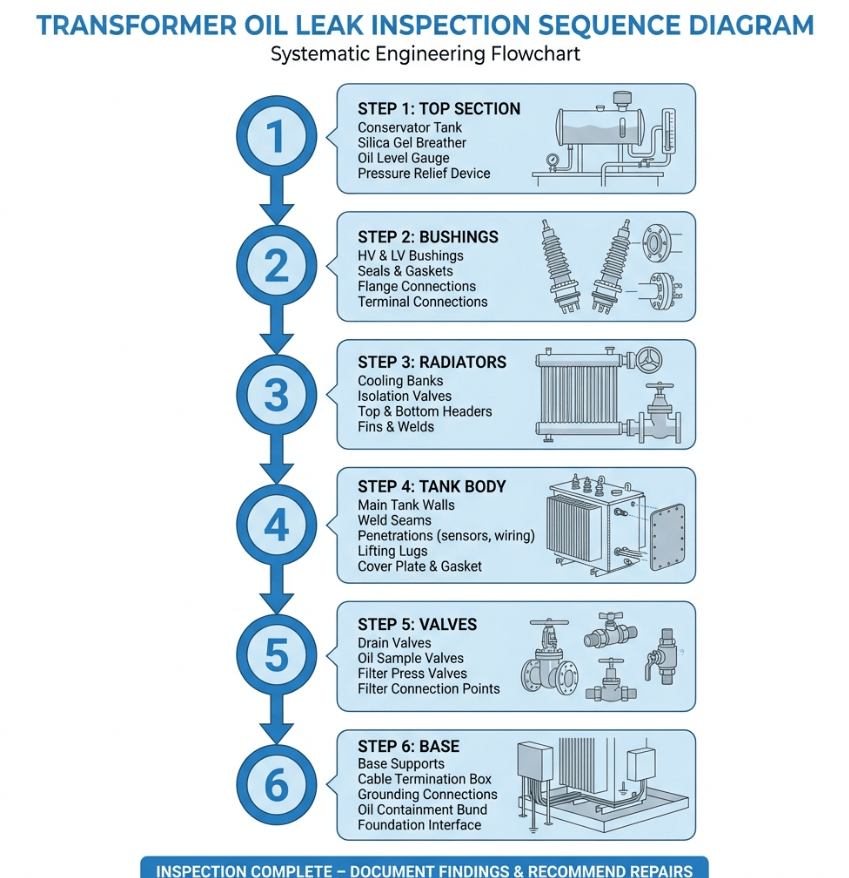
Transformer inspection points for oil leak detection
Inspection Sequence
Top Section
Start with conservator tank, breather connections, bushing turrets, and top cover gaskets. Oil
tends to migrate down from upper leaks.
Bushings
Check oil-to-air seals, mounting flanges, tap connections, and conduit boxes. Use mirror and
flashlight for underside inspection.
Radiators & Cooling
Examine radiator header connections, butterfly valve flanges, fan mounting areas, and
fin-to-header joints.
Tank Body
Inspect weld seams, nameplate attachments, lifting lugs, and any penetrations. Check for
corrosion, especially at base.
Valves & Accessories
Check all drain valves, sample valves, pressure relief devices, Buchholz relay connections, and
OLTC (if equipped).
Base & Ground
Examine bottom of tank, cable box connections, and ground-level evidence of dripping. Check bund
for accumulated oil.
Step-by-Step Repair Techniques
your organization’s lockout/tagout procedures. Ensure adequate ventilation and fire safety measures
are in place.
Gasket Replacement Procedure
Preparation
- De-energize and isolate transformer
- Lower oil level below repair area (if necessary)
- Gather correct gasket material, tools, and torque specifications
- Prepare containment for any oil spillage
Remove Cover/Component
- Mark bolt positions and component orientation
- Loosen bolts in star pattern to prevent warping
- Carefully remove component, supporting weight
- Protect exposed oil from contamination
Surface Preparation
- Remove old gasket completely (do not use metal scrapers on sealing surfaces)
- Clean flanges with appropriate solvent
- Inspect for corrosion, pitting, or warping
- Repair minor surface defects or replace component if severe
Install New Gasket
- Verify gasket material compatibility with oil type
- Apply thin coat of oil or gasket adhesive to hold in position
- Ensure gasket is centered with no overlaps or gaps
- Position component and hand-tighten bolts
Final Torquing
- Torque bolts in star/cross pattern per manufacturer specs
- Complete multiple passes (typically 3) to final torque
- Wait 24 hours and re-torque if using nitrile rubber gaskets
- Document torque values for records
Temporary Leak Repairs
When immediate shutdown is not possible, these temporary measures may contain minor leaks until
permanent repair:
| Method | Application | Duration | Limitations |
|---|---|---|---|
| Epoxy Putty | Small weld cracks, pinhole leaks | 6-12 months | Surface must be dry for adhesion |
| Pipe Clamp/Wrap | Piping connections, valve stems | 3-6 months | May not seal irregular surfaces |
| Injection Sealant | Gasket weeping, minor seepage | 6-18 months | Requires specialized equipment |
| External Sealant Tape | Pipe threads, small fittings | 1-3 months | Temporary only, must monitor |
at the earliest opportunity. Document all temporary repairs and include in outage planning.
Weld Repair Considerations
Tank weld repairs require careful planning and execution:
- Must be performed with transformer de-energized and drained
- Require hot work permits and fire watch
- Welder must be qualified per AWS D1.1 or equivalent
- Pre-heat and post-weld heat treatment may be necessary
- Vacuum or pressure testing required after repair
- Consider internal coating if corrosion was the cause
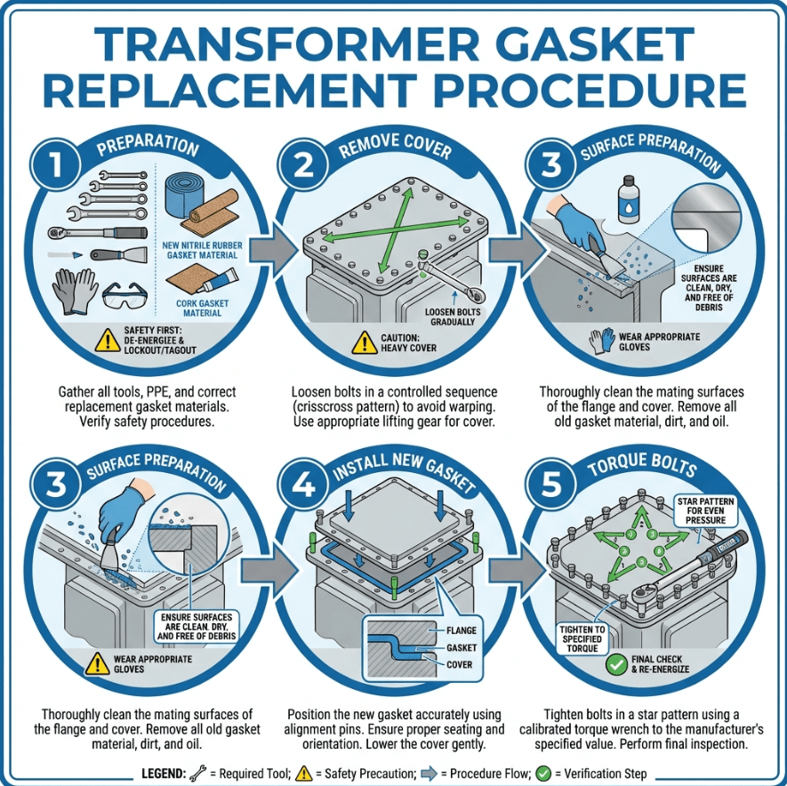
Step-by-step gasket replacement procedure illustration
Oil Leak Prevention Strategies
Scheduled Maintenance Program
| Frequency | Maintenance Activity | Reference |
|---|---|---|
| Daily | Visual inspection for leaks, MOG reading verification | Site SOP |
| Monthly | Check oil level in conservator and bushings, inspect breather | IEEE C57.93 |
| Annually | Thorough leak inspection, valve operation check, bolt torque verification | IEEE C57.93 |
| Every 3-5 Years | Gasket assessment, consider proactive replacement on critical units | Manufacturer |
| Every 10 Years | Complete gasket replacement on all accessible joints | Best Practice |
Design and Installation Best Practices
- Gasket Selection: Use high-quality gaskets rated for transformer oil service
(Viton® or similar for ester oils) - Proper Torquing: Use calibrated torque wrenches and follow manufacturer
specifications - Corrosion Protection: Apply appropriate coatings and manage drainage around
transformer - Vibration Isolation: Proper mounting and flexible connections reduce fatigue
failures - Temperature Management: Avoid rapid thermal cycling where possible
Oil Condition Monitoring
Regular oil testing helps identify issues before they cause leaks:
- Dissolved Gas Analysis (DGA): Annually for critical transformers
- Moisture Content: Should be <35ppm for safe operation
- Dielectric Breakdown Voltage (BDV): Minimum 35kV per ASTM D877
- Interfacial Tension: Indicates oil degradation and contamination
For detailed oil sampling procedures, see our guide: Transformer Oil
Testing Guide →
Environmental Compliance & Containment
Regulatory Requirements
Transformer oil leaks are subject to environmental regulations including:
- EPA SPCC (US): Spill Prevention, Control, and Countermeasure plans required for
facilities with aggregate oil storage >1,320 gallons - PCB Regulations: Oil containing >5ppm PCBs classified as hazardous waste in
many jurisdictions - Water Quality: Maximum allowable oil discharge typically <5mg /L to
environment - Reporting Requirements: Spills exceeding threshold quantities must be reported
Containment Solutions
Bund/Dike Systems
Concrete or steel containment surrounding transformer, sized to hold full oil volume plus 10%
freeboard
Bund Filters
Automatic oil/water separators allowing rainwater drainage while retaining oil (DrainEezy,
etc.)
Oil-Water Separators
Active treatment systems for larger installations or sites with multiple transformers
<1mg /L concentration in discharged water, well below the typical 5mg/L regulatory
limit. They provide passive, maintenance-free environmental protection.
Spill Response Procedure
Contain
Stop spread with absorbent materials, berms, or booms. Protect storm drains and waterways.
Control Source
If safe, reduce leak by valve closure, temporary sealing, or de-energization.
Report
Notify supervisor, environmental compliance, and regulatory agencies if required by spill
quantity.
Clean Up
Remove contaminated soil/materials for proper disposal. Document all actions taken.
Frequently Asked Questions
Q: What causes transformer oil leaks?
Transformer oil leaks are primarily caused by: 1) Gasket deterioration from age, heat cycling, and UV
exposure; 2) Weld cracks from thermal stress or manufacturing defects; 3) Bushing seal failures; 4)
Valve and fitting leaks; 5) Tank corrosion; 6) Physical damage from impact or vibration. Gasket
failures account for approximately 60-70% of all oil leaks.
Q: How do I detect a transformer oil leak?
Detect transformer oil leaks through: 1) Daily visual inspection for oil stains, drips, or wetness on
the tank and ground; 2) MOG (Magnetic Oil Gauge) readings showing declining oil levels; 3) Low oil
level alarms; 4) Infrared thermography to identify cold spots; 5) UV fluorescent dye testing for
pinpointing small leaks; 6) Oil consumption tracking over time.
Q: Can I repair a transformer oil leak without de-energizing?
Minor leaks can sometimes be temporarily addressed while energized using external sealants or clamps,
but this is NOT recommended for safety reasons. IEEE C57.93 and most utility protocols require
de-energization for any oil leak repair. Hot-line repair is extremely hazardous due to flash point
risks (mineral oil: >140°C) and should only be performed by specialized crews with proper safety
measures.
Q: How often should transformer oil levels be checked?
Transformer oil levels should be checked: 1) Daily for critical power transformers; 2) Weekly for
distribution transformers; 3) After any abnormal event (fault, overload, extreme temperature); 4)
Before and after maintenance. The MOG (Magnetic Oil Gauge) reading should be verified against
expected oil level at current ambient temperature. Any unexplained drop requires immediate
investigation.
Q: What environmental regulations apply to transformer oil leaks?
Transformer oil leaks are regulated under environmental protection laws including: EPA’s SPCC (Spill
Prevention, Control, and Countermeasure) regulations in the US requiring containment for units with
>1,320 gallons capacity; local water quality regulations; PCB disposal requirements if the oil
contains >5ppm PCBs. Oil discharge to environment must be <5mg /L (many bund systems achieve
<1mg/L). Violations can result in significant fines.
References & Standards
- IEEE
C57.93 – Guide for Installation and Maintenance of Liquid-Immersed Power Transformers - IEEE
C57.12.00 – Standard for Liquid-Immersed Distribution, Power, and Regulating
Transformers - ASTM D3487 –
Standard Specification for Mineral Insulating Oil Used in Electrical Apparatus - EPA SPCC Regulations – Spill Prevention, Control, and
Countermeasure - Electrical4U – Maintenance of Transformers: A Detailed Checklist
- Wikipedia – Transformer Oil