
Last year we shipped a batch of 200/5A current transformers to a submetering contractor in Southeast Asia. Two weeks later I got an urgent call: one of their technicians had disconnected a CT secondary terminal to test it without shorting the leads first. The resulting open-circuit voltage arced across the terminal block and destroyed not just the CT but the entire meter panel. Nobody was injured, but the cost in downtime and replacement equipment ran to several thousand dollars.
That incident is why I take CT wiring so seriously. The physics at work are counterintuitive — it looks like a low-voltage secondary circuit, but an open-circuited CT under load is one of the most dangerous situations in a metering installation. This guide covers every configuration you’ll encounter in the field, with complete current transformer wiring diagrams for single-phase, 3-phase CT meter wiring, 2CT configurations, and solar net metering, along with the polarity rules and verification steps that keep installations safe and accurate.
If you need background on CT types and ratings, see our current transformer overview. For control transformer wiring (separate topic), see our control transformer wiring guide.
📋 Table of Contents
- CT Terminal Markings: P1/P2, S1/S2, H1/X1, K/L Explained
- ⚠️ Open-Circuit Danger: The #1 Safety Rule
- Single-Phase CT Metering Wiring Diagram
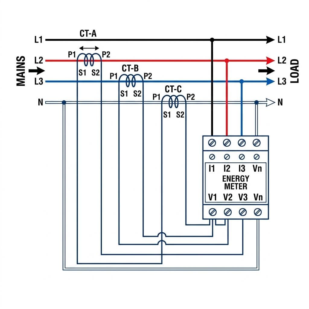
- 3-Phase CT Meter Wiring Diagram (3CT — Standard)
- 3-Phase CT Meter Wiring Diagram (2CT — Aron/Blondel Method)
- CT Ratio Selection Table
- Solar Net Metering CT Wiring Diagram
- Step-by-Step Wiring Procedure
- Post-Installation Verification & Polarity Check
- Troubleshooting: Wrong Reading / Backwards Count / No Display
- FAQ
1. CT Terminal Markings: P1/P2, S1/S2, H1/X1, K/L Explained
Before touching a single wire, you must understand CT terminal markings. Three different standards are in use worldwide — all mean the same thing but use different letters. Mixing them up is the single most common cause of reversed-polarity metering errors in the field.

| Standard | Primary Terminal (Current Enters) | Primary Terminal (Current Exits) | Secondary (+) Terminal → Meter Current In | Secondary (−) Terminal → Meter Current Out |
|---|---|---|---|---|
| IEC 61869 | P1 | P2 | S1 | S2 |
| ANSI / IEEE C57.13 | H1 | H2 | X1 | X2 |
| Old British / K/L | K (= P1) | L (= P2) | k (= S1) | l (= S2) |
The universal polarity rule: Current entering the primary at P1 produces current flowing out of S1 toward the meter. P1 and S1 are always the same instantaneous polarity — both at their positive peak simultaneously. This is called subtractive polarity per IEEE C57.13 (Instrument Transformers Standard) and is standard for all instrument transformers. Though a CT secondary operates at low nominal voltage under normal conditions, an open-circuit or fault condition on the secondary winding can result in extremely high voltage at the terminals — detailed in Section 2.
For a deeper dive into CT theory and measurement principles, All About Circuits has a solid overview of current transformer operation. For IEC accuracy class definitions used in revenue metering, refer to IEC 61869-2 (Instrument Transformers — CTs).
2. ⚠️ Open-Circuit Danger: The #1 Safety Rule
⛔ CRITICAL SAFETY RULE — Never Open-Circuit a CT Secondary Under Load
A current transformer is a constant current source on its secondary side. When the primary conductor carries current but the secondary circuit is broken (open), the CT core magnetizes to saturation trying to maintain ampere-turn balance. The result is a dangerously high voltage at the secondary terminals — potentially hundreds to thousands of volts depending on the CT ratio and primary current.
Consequences of an open-circuited CT secondary:
- Electric shock hazard at “low voltage” secondary terminals
- Insulation puncture and destruction of the CT winding
- Core overheating and fire risk
- Irreversible CT damage (core magnetization error)
Before disconnecting any CT secondary lead: Always install a shorting link or CT shorting block across S1–S2 first to provide a zero-resistance secondary path.
| Situation | Rule | Method |
|---|---|---|
| Replacing/testing meter while CT primary is live | Short S1–S2 before disconnecting meter leads | CT shorting block or jumper wire across S1–S2 |
| Installing new CT on live conductor | Short S1–S2 during installation, connect meter first, then remove short | Factory-installed shorting clip (many split-core CTs include this) |
| Storing a used CT | Keep S1–S2 shorted during storage | Wire jumper or terminal block shorting link |
| Test terminal blocks (TTBs) for metering panels | Use TTBs with integral shorting facility | Test terminal block with shorting bar that shorts CT before breaking circuit |
3. Single-Phase CT Metering Wiring Diagram
Single-phase CT metering is the simplest configuration: one CT on the phase conductor, a single-phase meter receiving secondary current and line voltage.
// Single-Phase CT Meter Wiring (text diagram):
MAINS L ──→ [P1 CT P2] ──→ LOAD L
MAINS N ──────────────────────────→ LOAD N
CT S1 ──→ Meter I+ (current in terminal)
CT S2 ──→ Meter I− (current out / common)
L (via fuse) ──→ Meter V+ (voltage in)
N ─────────→ Meter V− (voltage neutral)
⚠ S1–S2 must NEVER be open while L carries current
| Connection Point | Terminal on Meter | Wire | Notes |
|---|---|---|---|
| CT S1 | I1 (current input, positive) | 2.5mm² copper | Short cable run — keep under 5m for Class 0.5 accuracy |
| CT S2 | I2 (current input, common) | 2.5mm² copper | Both S2 and neutral voltage terminal often share common bus |
| Line L (via fuse) | V (voltage input) | 1.5mm² copper | Fuse: 1–6A glass or ceramic, on line side only |
| Neutral N | N (voltage neutral) | 1.5mm² copper | Unfused neutral |
4. 3-Phase CT Meter Wiring Diagram (3CT — Standard Configuration)
The 3CT configuration places one current transformer on each phase. This is the correct method for all 4-wire wye (star) systems (120/208V or 277/480V) and any system where loads may be unbalanced between phases.
// 3-Phase 3CT Meter Wiring (text diagram — 4-wire Wye):
MAINS L1 ──→ [P1 CT-A P2] ──→ LOAD L1
MAINS L2 ──→ [P1 CT-B P2] ──→ LOAD L2
MAINS L3 ──→ [P1 CT-C P2] ──→ LOAD L3
MAINS N ──────────────────────→ LOAD N
CT-A S1 ──→ Meter terminal 1 (L1 current in)
CT-A S2 ──→ Meter terminal 3 (L1 current out)
CT-B S1 ──→ Meter terminal 4 (L2 current in)
CT-B S2 ──→ Meter terminal 6 (L2 current out)
CT-C S1 ──→ Meter terminal 7 (L3 current in)
CT-C S2 ──→ Meter terminal 9 (L3 current out)
L1 + [Fuse] ──→ Meter terminal 2 (L1 voltage)
L2 + [Fuse] ──→ Meter terminal 5 (L2 voltage)
L3 + [Fuse] ──→ Meter terminal 8 (L3 voltage)
N ──────────→ Meter terminal 11 (Neutral)
⚠ All three CT secondaries must remain shorted if meter is disconnected
Notes on terminal numbering: Terminal numbers vary by meter manufacturer. The sequence above follows the common IEC energy meter layout (where terminals 1–3 = phase A current group, 2 = voltage tap, etc.). Always confirm against your specific meter’s nameplate diagram found under the terminal cover.
| Connection | Function | Cable Spec | Fuse Required? |
|---|---|---|---|
| CT-A/B/C S1 → Meter I-in | Phase current measurement input (positive) | 2.5mm² stranded copper | No — never fuse the CT secondary |
| CT-A/B/C S2 → Meter I-out | Phase current measurement return | 2.5mm² stranded copper | No |
| L1/L2/L3 → Meter V-in | Voltage reference for each phase | 1.5mm² copper | Yes — 1–6A per phase, external |
| N → Meter neutral terminal | Voltage reference common | 1.5mm² copper | No — never fuse the neutral |
5. 3-Phase CT Meter Wiring Diagram (2CT — Aron/Blondel Method)
For 3-wire delta systems (no neutral conductor), two CTs can accurately measure total three-phase power. This is the Aron connection (also called Blondel’s theorem in practice): with N wires, you need N−1 measuring elements. For a 3-wire system: 3 − 1 = 2 CTs.
// 3-Phase 2CT Meter Wiring (Aron/Blondel — 3-wire Delta):
MAINS L1 ──→ [P1 CT-A P2] ──→ LOAD L1
MAINS L2 ──────────────────────→ LOAD L2 (no CT on L2)
MAINS L3 ──→ [P1 CT-C P2] ──→ LOAD L3
CT-A S1 ──→ Meter terminal I1+ (element 1, current in)
CT-A S2 ──→ Meter terminal I1− (element 1, current out)
CT-C S1 ──→ Meter terminal I2+ (element 2, current in)
CT-C S2 ──→ Meter terminal I2− (element 2, current out)
L1 + [Fuse] ──→ Meter V1 (voltage element 1 reference)
L2 ──────────→ Meter V-common (shared voltage reference)
L3 + [Fuse] ──→ Meter V2 (voltage element 2 reference)
| Feature | 3CT Configuration | 2CT Aron Configuration |
|---|---|---|
| Number of CTs | 3 | 2 |
| Suitable system | 3-wire delta OR 4-wire wye | 3-wire delta only (balanced or near-balanced) |
| Accuracy with unbalanced load | Full accuracy regardless of balance | Accurate only for balanced 3-wire systems |
| Neutral required | Yes (for 4-wire wye) | No (3-wire delta only) |
| Common application | Industrial 4-wire 277/480V service | Industrial 3-wire 480V delta, legacy installations |
| Phase B current measured directly? | Yes | No — computed internally by meter |
| Revenue metering accepted? | Yes — all utility applications | Depends on utility — verify before installation |
6. CT Ratio Selection Table
Choosing the correct CT ratio is critical for meter accuracy. The secondary output must match the meter’s rated current input (almost always 5A for revenue-grade meters). The primary rating must be selected so that the transformer connected load current falls between 20% and 120% of CT rated primary current for Class 0.5 or better accuracy.
CT Primary Rating ≥ 1.2 × Maximum Expected Load Current (A)

Secondary output at full load = CT Primary Rating ÷ CT Ratio Denominator = 5A (standard)

Minimum accurate current = 20% × CT Primary Rating
| Service Size (A) | Recommended CT Ratio | Secondary Output at Full Load | Minimum Accurate Load | Accuracy Class | Typical Application |
|---|---|---|---|---|---|
| Up to 50A | 50/5 (or 75/5) | 5A | 10A (20%) | Class 0.5 | Small commercial, residential submetering |
| 51–100A | 100/5 | 5A | 20A | Class 0.5 | Standard commercial circuits |
| 101–200A | 200/5 | 5A | 40A | Class 0.5 | Commercial distribution panels |
| 201–400A | 400/5 | 5A | 80A | Class 0.5 | Industrial feeders |
| 401–600A | 600/5 | 5A | 120A | Class 0.5 | Large industrial services |
| 601–1000A | 1000/5 | 5A | 200A | Class 0.5 | MV transformer secondaries |
| 1001–1500A | 1500/5 | 5A | 300A | Class 0.5S | Large industrial/utility metering |
| 1501–2000A | 2000/5 | 5A | 400A | Class 0.5S | Utility revenue metering |
| 2001–3000A | 3000/5 | 5A | 600A | Class 0.2S | HV revenue metering |
| 3001–5000A | 5000/5 | 5A | 1000A | Class 0.2S | Grid-level revenue metering |
Burden consideration: The total secondary winding circuit resistance (CT internal resistance + cable resistance + meter input resistance) must not exceed the CT’s rated burden in VA. Exceeding the burden degrades accuracy. For a 200/5 CT rated at 15VA burden: at 5A secondary, maximum circuit impedance = 15VA ÷ 5A² = 0.6Ω. For 10 meters of 2.5mm² cable (round trip 20m): R = 0.0175 × 20 ÷ 2.5 = 0.14Ω — well within limit.
7. Solar Net Metering CT Wiring Diagram
Solar net metering requires bidirectional current measurement — the CT and meter must accurately register both energy import (from grid) and energy export (from solar array to grid). Most modern digital meters support bidirectional measurement natively; older mechanical meters do not.

Net Metering CT Placement Rules
| Rule | Correct Practice | Common Mistake | Consequence of Mistake |
|---|---|---|---|
| CT position relative to solar tie-in | Install CTs at the service entrance, on the utility side of the solar inverter connection point | Installing CTs on the load side of the solar tie-in | Meter only sees net of solar+load current; cannot measure gross generation for incentive billing |
| P1 orientation | P1 faces the utility/grid (mains direction), P2 faces load | P1 faces the load/inverter side | Import registers as export and vice versa — meter reads negative energy during high consumption |
| Meter type | Bidirectional digital meter (supports Register 1 = Import, Register 2 = Export) | Single-direction mechanical disk meter | Meter disk spins backward during export — physically damages register mechanism in many models |
| CT ratio for solar service | Size based on maximum service current (utility capacity), not solar inverter output | Sizing CT based on inverter output AC rating only | CT undersized for grid import peaks; measurement errors during high consumption periods |
// Solar Net Metering 3-Phase CT Wiring (text diagram):
UTILITY L1 ──→ [P1 CT-A P2] ─┬──→ SOLAR INVERTER OUTPUT L1
UTILITY L2 ──→ [P1 CT-B P2] ─┼──→ SOLAR INVERTER OUTPUT L2
UTILITY L3 ──→ [P1 CT-C P2] ─┴──→ SOLAR INVERTER OUTPUT L3
└──→ PANEL LOADS
CT-A S1 ──→ Meter I1+ | CT-A S2 ──→ Meter I1−
CT-B S1 ──→ Meter I2+ | CT-B S2 ──→ Meter I2−
CT-C S1 ──→ Meter I3+ | CT-C S2 ──→ Meter I3−
L1/L2/L3 [via fuses] ──→ Meter voltage inputs
N ──→ Meter neutral terminal
⚠ CT P1 must face the UTILITY/GRID — not the load/inverter
8. Step-by-Step CT Meter Wiring Procedure
- De-energize and LOTO. Apply lockout/tagout on the upstream supply. Verify zero voltage at all conductors with a CAT III multimeter. Verify zero voltage on all CT primary conductors before handling any CT.
- Select and verify CTs. Confirm all three CTs have identical ratios (e.g., all 200/5). Ratio mismatch between phases causes systematic measurement error on the phase with the wrong CT. Check accuracy class (Class 0.5 minimum for revenue metering per IEC 61869-2).
- Install CTs on primary conductors — polarity first. Mount each CT with P1 facing the source (mains/utility) side. For toroidal/window CTs: pass the conductor through the CT window from P2 side toward P1 side (the conductor exits the CT on the P1 face in the direction of current flow toward the source). For split-core CTs: observe the arrow marking “→ LOAD” or “→ LINE” printed on the CT body.
- Verify CT orientation before closing split-core. Before snapping shut a split-core CT, double-check: current flowing toward the load should be flowing in the direction that exits the CT through the P2 face. If unsure, mark the conductor with tape indicating current direction.
- Install CT shorting blocks or test terminal blocks. Connect a shorting link across each CT’s S1–S2 terminals. Do not remove this short until the meter is fully connected and the secondary circuit is complete.
- Run CT secondary cables to the meter. Use minimum 2.5mm² stranded copper cable. Keep all three phase runs to equal lengths where possible to maintain equal burden. Do not route CT secondary cables alongside high-voltage conductors (induced interference can affect accuracy).
- Connect CT secondary to meter — S1 first. Connect S1 of each CT to the corresponding current-in terminal on the meter. Then connect S2 to the current-out/common terminal. Torque terminals to specification (typically 1–1.5 Nm for M3 screws on metering terminal blocks).
- Connect voltage inputs with fuses. Install individual fuses (1–6A) in each phase voltage feed to the meter. Connect L1, L2, L3 through fuses to the meter’s voltage terminals. Connect neutral (unfused) to the meter neutral terminal.
- Remove CT shorting links. Only after all meter connections are confirmed complete, remove the shorting links from each CT’s S1–S2 in sequence. Tighten terminal screws after removing each short.
- Re-energize and verify. Restore power under controlled conditions. Check as described in Section 9 below.
9. Post-Installation Verification & Polarity Check
After energizing, perform these checks in sequence:
| Check | Expected Result | If Wrong |
|---|---|---|
| 1. Phase indicator LEDs | All three phase indicators (RST or L1/L2/L3) lit solid | If off: one or more voltage fuses blown, or voltage connection missing. If flashing: phases in wrong sequence — swap two of the voltage input leads (voltage only, not current) |
| 2. kWh register direction | Energy register incrementing (counting up) with load connected | If decrementing: CT polarity reversed on one or more phases. Swap S1 and S2 leads on the suspected CT(s) |
| 3. Power factor reading | Near 1.0 for resistive loads (water heaters, electric baseboard); 0.8–0.95 lagging for motor loads | If reads negative (e.g., −0.98): one CT has reversed polarity — swap S1/S2 on that phase |
| 4. Current reading vs. clamp meter | Meter display × CT ratio = clamp meter reading ±2% for Class 0.5 | If off by exactly 2×: CT ratio incorrect (check nameplate). If reading zero: S1/S2 connection open or swapped with another phase |
| 5. Individual phase comparison | All three phases showing similar kW contribution for balanced loads | If one phase reads zero: verify that phase’s CT S1/S2 connection and fuse. If one phase reads double: two CTs connected to same meter input |
10. Troubleshooting: Wrong Reading / Backwards Count / No Display
| Symptom | Most Likely Cause | Diagnostic | Fix |
|---|---|---|---|
| Meter counts backwards | CT polarity reversed (one or more CTs have P1/P2 swapped, or S1/S2 swapped at meter) | Check the power factor register — it will show negative or >1.0. Use a clamp meter to verify current direction on the secondary lead at the meter | Swap S1 and S2 leads at the meter terminal for the reversed phase (do not reverse at CT — always short first) |
| Reading is exactly half expected | 2CT meter wired but only one CT connected; or one CT secondary open-circuited (no current path) | Check S1/S2 connections for the missing phase — continuity test on each secondary circuit | Verify and reconnect the missing CT secondary. Ensure no broken lead, blown shorting terminal, or loose screw |
| Reading off by factor of CT ratio | Meter CT ratio multiplier not programmed, or wrong CT installed (e.g., 100/5 instead of 200/5) | Check meter programming for CT ratio setting. Compare with CT nameplate | Reprogram meter with correct CT primary ratio, or replace CT with correct ratio |
| No display / meter dead | Voltage input fuse blown; missing neutral; incorrect voltage wiring | Check each voltage input fuse continuity. Verify voltage between each phase input and the neutral terminal at the meter | Replace blown fuse. Verify neutral is connected and not open. Verify voltage inputs match meter rated voltage |
| One phase always reads low | High CT secondary burden (long cable run); CT approaching saturation (overloaded primary) | Measure voltage across S1–S2 at the CT and at the meter — excessive voltage drop indicates high burden. Verify primary current is within CT rating | Reduce cable length or increase to 4mm² cable if run is long. Replace CT with higher-ratio unit if primary is overloaded |
| Meter shows correct kW but wrong kWh over time | CT accuracy class mismatch; significant load below CT’s minimum accurate current (20% threshold) | Log load profile over 24 hours — if most consumption is below 20% of CT rated primary, accuracy will be poor | Replace with smaller CT ratio that better matches actual load range, or use Class 0.2S CTs with extended low-current accuracy |
11. Frequently Asked Questions
What does P1, P2, S1, S2 mean on a current transformer?
P1 and P2 are the primary winding terminals — the terminals through which the primary conductor (high-voltage, high-current line) passes or connects. S1 and S2 are the secondary winding terminals connected to the meter or relay. By IEC 61869 convention, P1 (also marked K on older British-standard CTs) is the terminal where the primary current enters, and S1 (also marked k) is the corresponding positive secondary terminal. ANSI IEEE C57.13 uses H1/H2 for primary and X1/X2 for secondary with identical polarity convention.
Can I use 2 CTs instead of 3 for a 3-phase meter?
For a 3-wire delta system only, yes. The Aron (Blondel) 2CT method places CTs on two of the three phases; the meter computes the third phase internally. This is accurate only for balanced or near-balanced 3-wire systems. For 4-wire wye systems (which includes all services with a neutral conductor), always use 3 CTs — one per phase. The 2CT method will introduce measurement errors proportional to load unbalance on wye systems.
What happens if I leave a CT secondary open-circuit?
An open-circuited CT secondary is a serious safety hazard. With the primary conductor carrying current but the secondary circuit open, the CT core attempts to maintain magnetic flux balance but has no secondary current path. The core drives toward saturation on each half-cycle, and the CT’s secondary winding develops a very high induced voltage — potentially hundreds of volts for distribution-class CTs, even higher for high-ratio units. This causes insulation failure, electric shock risk, and core overheating. Always use a shorting link across S1–S2 before opening the secondary circuit.
How do I know if my CT polarity is correct after installation?
After energizing with a known load: (1) The kWh meter should increment (count upward) not decrement. Backward counting means reversed polarity on one or more CTs. (2) The power factor reading should be near 1.0 for resistive loads (electric heaters, etc.). A reading near −1.0 confirms reversed polarity. (3) For verification without a reference load, use a clamp meter on the CT secondary lead at the meter connection — the CT current should flow from S1 toward the meter during the positive half of the AC cycle.
What size cable should I use for CT secondary wiring?
Use 2.5mm² stranded copper (approximately 14 AWG equivalent) for CT secondary wiring up to 10 meters one-way run. For longer runs (10–30 meters), calculate the cable burden: R_cable = 0.0175 × (2 × run length in meters) ÷ (cable cross-section in mm²). Verify that R_cable plus the meter’s current input impedance does not exceed the CT’s rated burden class (typically 5–15 VA). Exceeding rated burden degrades accuracy — for long runs, increase to 4mm² or 6mm² cable to reduce resistance.
What CT ratio should I use for my meter?
The CT secondary output must match the meter’s rated current input — nearly always 5A for revenue-grade meters. Select the CT primary rating at 120–125% of your maximum expected load current. Examples: 150A service → 200/5 CT; 400A service → 500/5 CT. For accuracy, the normal operating current should fall between 20%–120% of the CT’s rated primary. Operating below 20% of rated primary typically causes accuracy to fall below Class 0.5.
Need current transformers or CT metering assemblies for your project?
At Transformer4U, we supply metering-grade current transformers from 50/5 to 5000/5A — IEC 61869-2 Class 0.5 and 0.2S, split-core and solid-core, with full test certificates. Our engineering team can advise on CT selection, burden calculation, and wiring configuration for your specific installation. Request a quote or technical consultation →
Key Takeaways
- Always install CTs with P1 facing the mains (source) and P2 facing the load — this sets the correct polarity for the meter.
- Never open-circuit the CT secondary while primary current flows. Short S1–S2 before disconnecting any secondary lead.
- For 4-wire wye systems, always use 3 CTs (one per phase). The 2CT Aron method is valid only for balanced 3-wire delta systems.
- CT secondary wiring must not be fused. Voltage input wiring must be fused individually on each phase (1–6A).
- Use 2.5mm² stranded copper for CT secondary cables; calculate burden to verify it stays within the CT’s rated class.
- Select CT primary rating at 120–125% of maximum load current. Operating below 20% of CT rated primary degrades accuracy below Class 0.5.
- After installation, verify polarity: meter should count forward, power factor near 1.0 on resistive loads, and phase indicators all lit solid.
Related Articles
- Current Transformer: Types, Ratios & Selection Guide
- Control Transformer Wiring Guide: H1/H2/X1/X2, NEC Fuse Sizing
- 3-Phase Transformer Bank Wiring: Delta, Wye & 6 Mistakes
- Contact Our Engineering Team
About the author: Tan is a transformer engineer at Transformer4U, a manufacturer of toroidal, EI, dry-type, and oil-immersed transformers with over 12 years of production and commissioning experience. He has designed and tested CT metering assemblies for industrial and utility-scale installations across North America, Europe, and Southeast Asia.