
Everything you need to know about current transformers including construction, types, accuracy classes,
applications, and safety considerations

A current transformer (CT) is an essential instrument transformer used in electrical systems to measure and monitor alternating current (AC) in power system applications.
Current transformers reduce high primary current levels to a safe, standardized secondary current
that can be easily measured by meters and protective relays.
Unlike power transformers, a transformer CT is designed specifically for measuring alternating current AC with high accuracy while providing electrical isolation between high
voltage power circuits and low-voltage measurement equipment.
proportional to the primary current, allowing accurate measurement without direct connection to
high-voltage circuits.
What is a Current Transformer?
A current transformer is a type of instrument transformer that produces a current in its
secondary winding that is proportional to the primary current flowing
through the primary winding. The primary winding is connected in series with the primary
conductor carrying the current to be measured.
Basic Components
- Magnetic Core: Made from laminated silicon steel to minimize losses
- Primary Winding: Usually a single turn or few turns carrying the line current
- Secondary Winding: Many turns of fine wire, typically rated 1A or 5A
- Insulation: Separates primary and secondary and provides safety isolation
How a Current Transformer Works
- AC current flows through the primary conductor (line current)
- This creates an alternating magnetic field in the magnetic core
- The changing magnetic flux induces a current in the secondary winding
- The secondary current is inversely proportional to the number of turns ratio
Current Ratio Formula:
Is = Ip × (Np / Ns)
Where: Is = Secondary current, Ip = Primary current, Np = Primary turns, Ns = Secondary turns
Types of Current Transformers
1. Wound Current Transformer
A wound current transformer has both primary and secondary windings wound around a
laminated magnetic core. This type allows precise control over the transformation ratio.
| Feature | Specification |
|---|---|
| Primary Turns | Multiple turns (customizable) |
| Accuracy | Highest precision available |
| Applications | Laboratory, precision metering |
| Cost | Higher than other types |
2. Bar Type Current Transformers
Bar type current transformers have a copper or aluminum bus bar as the primary
conductor, which passes through the center of the core. The bar is permanently fixed through the CT
window.
| Feature | Specification |
|---|---|
| Primary | Fixed bar (single turn) |
| Current Range | Up to several thousand amperes |
| Installation | Bolted to bus bar or switchgear |
| Best For | High current applications |
3. Toroidal (Window/Ring Type) Current Transformers
Toroidal CTs have a ring-shaped core with secondary windings but no dedicated primary. The primary
conductor passes through the window, making installation simple.
| Feature | Specification |
|---|---|
| Primary | Conductor passed through window |
| Turns Ratio | Conductor passes = primary turns |
| Flexibility | High – can clamp around existing cables |
| Common Use | Energy metering, clamp meters |
4. Split Core Current Transformers
Split core current transformers have a hinged or separable core that can be opened and installed
around existing conductors without disconnecting the circuit.
| Feature | Specification |
|---|---|
| Core Design | Hinged or two-piece core |
| Installation | Non-invasive, no circuit interruption |
| Accuracy | Slightly lower due to air gaps |
| Best For | Retrofits, temporary monitoring |

Current Transformer Specifications
Standard Current Ratios
| Primary Current | Secondary Current | Ratio |
|---|---|---|
| 50 A | 5 A | 50:5 (10:1) |
| 100 A | 5 A | 100:5 (20:1) |
| 200 A | 5 A | 200:5 (40:1) |
| 400 A | 5 A | 400:5 (80:1) |
| 800 A | 5 A | 800:5 (160:1) |
| 1000 A | 5 A | 1000:5 (200:1) |
| 2000 A | 5 A | 2000:5 (400:1) |
Accuracy Classes (IEC 61869-2)
| Class | Ratio Error at 100% Current | Application |
|---|---|---|
| 0.1 | ±0.1% | Precision laboratory |
| 0.2 | ±0.2% | Revenue metering |
| 0.5 | ±0.5% | General metering |
| 1.0 | ±1.0% | Industrial metering |
| 3.0 | ±3.0% | Indication only |
| 5P10 | ±5% (up to 10× rated) | Protection relays |
| 10P20 | ±10% (up to 20× rated) | Protection applications |
Key Specifications
- Rated Voltage: Maximum system voltage (e.g., 0.6kV, 11kV, 33kV)
- Rated Primary Current: Standard values: 10, 15, 20, 25, 30, 50, 75, 100 A (and multiples)
- Rated Secondary Current: Usually 1A or 5A
- Burden (VA): Power consumed by secondary circuit (1.5, 3, 5, 10, 15, 30 VA)
- Thermal Rating Factor (RF): Overload capacity (typically 1.2 to 2.0)
Applications of Current Transformers
Power System Protection
Current transformers provide current signals to protective relays for:
- Overcurrent protection
- Differential protection
- Ground fault detection
- Circuit breaker trip circuits
Metering and Measurement
- Revenue-grade energy metering
- Power system monitoring
- Power quality analysis
- Load surveys
Industrial Applications
- Motor protection and control
- Variable frequency drive monitoring
- Process control systems
- Industrial automation
CT Safety Considerations
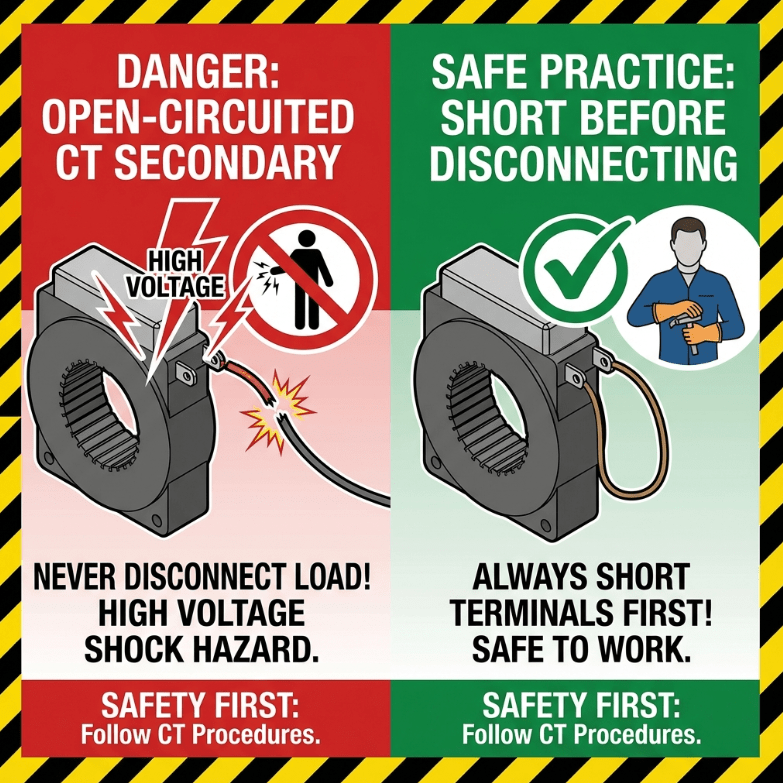
⚠️ CRITICAL: Never Open-Circuit a CT Secondary
When current is flowing through the primary winding, the secondary winding must
NEVER be left open-circuit. An open secondary causes:
- Dangerous high voltages (potentially thousands of volts)
- Core saturation and overheating
- Permanent damage to the CT
- Risk of electrical shock or fire
Always short-circuit the secondary terminals before disconnecting measuring equipment.
Installation Safety Guidelines
- Always verify CT polarity (P1-P2, S1-S2 markings)
- Ground the secondary circuit at ONE point only
- Use appropriately rated test blocks
- Size secondary winding cables to minimize voltage drop
- Verify burden does not exceed CT rating
CT vs PT Comparison
| Factor | Current Transformer (CT) | Potential Transformer (PT) |
|---|---|---|
| Purpose | Measure current | Measure voltage |
| Primary Connection | Series with load | Parallel with line |
| Secondary Rating | 1A or 5A | 110V (typically) |
| Open Circuit Risk | DANGEROUS – high voltage | No hazard |
| Core Impedance | Very low (near short circuit) | Very high |
🏭 Factory Experience:With over 15 years in instrument transformer manufacturing, we’ve observed common CT selection mistakes:
- Undersized Burden: Many installations exceed the rated burden, reducing accuracy. Always
calculate total burden including connecting cables. - Wrong Accuracy Class: Using protection-class CTs for revenue metering results in billing
errors. Match the accuracy class to application requirements. - Ignoring Temperature Effects: CT accuracy varies with temperature. For outdoor
installations in extreme climates, consider temperature-rated CTs. - Poor Polarity Verification: Incorrect CT polarity causes protection relay malfunction.
Always verify polarity during commissioning.
Frequently Asked Questions
What is a current transformer used for?
A current transformer (CT) is used to step down high primary currents to a safe, measurable level (typically 1A or
5A) for metering, protection, and control in electrical power systems.
How does a current transformer work?
A current transformer works by electromagnetic induction. When AC current flows through the primary conductor, it
creates a changing magnetic field in the core that induces a proportional current in the secondary winding.
What is the difference between a current transformer and a power transformer?
A current transformer is designed to measure current with high accuracy and has a fixed secondary current rating. A
power transformer transfers power between circuits and its secondary current varies with load.
Can a current transformer be used for DC current?
No, standard current transformers only work with alternating current (AC). The principle of electromagnetic induction
requires a changing magnetic field, which DC cannot provide. For DC measurement, Hall effect sensors or DC current
transducers are used.
What happens if a CT secondary is left open?
If the secondary of a current transformer is left open while primary current flows, dangerous high voltages
(potentially several kilovolts) will develop across the secondary terminals. This can cause insulation breakdown,
fire, and electric shock hazards.
Related Articles
- Single Phase Distribution
Transformer Guide - Distribution
Transformer Sizing Calculator - Power
Transformer Specifications Explained - Transformer
Construction: Core & Windings
References
- IEC 61869-2 – Instrument Transformers: Current
Transformers - IEEE C57.13 – Standard Requirements for
Instrument Transformers - NFPA 70 – National Electrical Code
Disclaimer: This information is provided for educational purposes. Current transformers involve high voltages and
currents. Always follow proper safety procedures and consult qualified electrical engineers for specific
applications.