
Comprehensive guide to auto transformers – single winding design for efficient voltage adjustment
An auto transformer is a type of electrical transformer with only one winding that serves as both
the primary and secondary. The term “auto” comes from Greek meaning “self” – referring to the single coil acting
alone, not any automatic mechanism.
This complete guide covers auto transformer construction, working principle, advantages and
disadvantages, copper savings, and applications including motor starting and the Variac.
voltage outputs. Part of the winding is common to both primary and secondary circuits, making it smaller and more
efficient than conventional two-winding transformers.
What is an Auto Transformer?
An auto transformer differs from conventional transformers by using a single continuous winding
instead of separate primary and secondary windings. The primary voltage is applied across the full winding, while
the secondary voltage is taken from a tap point along the winding.
Auto Transformer vs Conventional Transformer
| Feature | Auto Transformer | Conventional Transformer |
|---|---|---|
| Windings | Single winding | Separate primary and secondary |
| Electrical Isolation | No isolation | Complete isolation |
| Size | Smaller and lighter | Larger and heavier |
| Cost | Lower cost | Higher cost |
| Efficiency | Higher (less losses) | Lower (more losses) |
| Voltage Ratio | Best for ratios close to 1:1 | Any ratio |
Auto Transformer Working Principle
The auto transformer operates on the same electromagnetic induction principle as conventional transformers, but with
a single continuous winding.
Basic Construction
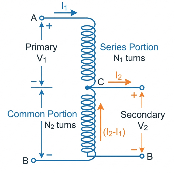
Consider a winding AB with total turns N1. A tap is taken at point C, creating section BC with N2 turns:
- Primary voltage V1 is applied across terminals A and B (full winding)
- Secondary voltage V2 is taken across terminals C and B (portion of winding)
- The section BC is common to both primary and secondary circuits
Voltage Ratio Formula:
V2/V1 = N2/N1 = k (transformation ratio)
Current Relationship:
Current in common winding = I2 – I1
Step-Down Auto Transformer
When the secondary voltage is less than primary (V2 < V1):
- Primary is connected across the full winding
- Secondary is tapped from a portion of the winding
- Common section carries difference current (I2 – I1)
Step-Up Auto Transformer
When the secondary voltage is greater than primary (V2 > V1):
- Primary is connected to a portion of the winding
- Secondary is taken from the full winding
- Connection is simply reversed
Copper Savings in Auto Transformer
One major advantage of auto transformers is significant copper savings compared to two-winding transformers.
Saving = k × 100% (where k = N2/N1 = transformation ratio)
Copper Savings Examples
| Voltage Ratio | Transformation Ratio (k) | Copper Saving |
|---|---|---|
| 220V to 200V | 0.91 | 91% |
| 230V to 110V | 0.48 | 48% |
| 480V to 240V | 0.50 | 50% |
| 11kV to 6.6kV | 0.60 | 60% |
Key insight: Auto transformers are most economical when the voltage ratio is close to 1:1
(transformation ratio above 0.5).
Advantages of Auto Transformers
| Advantage | Explanation |
|---|---|
| Smaller Size | Less copper and smaller core required |
| Lower Cost | Reduced material and manufacturing cost |
| Higher Efficiency | Lower I²R losses and core losses |
| Better Voltage Regulation | Lower leakage reactance and resistance |
| Lower Exciting Current | Smaller magnetizing current required |
| Variable Voltage Output | Multiple taps allow voltage adjustment |
Disadvantages of Auto Transformers
| Disadvantage | Explanation |
|---|---|
| No Electrical Isolation | Primary and secondary are electrically connected |
| Safety Concerns | Full primary voltage can appear at secondary if winding opens |
| Higher Short Circuit Current | Low impedance results in larger fault currents |
| Common Neutral | Cannot isolate neutrals of primary and secondary |
| Limited Voltage Ratio | Economical only for ratios close to 1:1 |
appears at the secondary terminals. This can damage connected equipment and pose serious safety hazards.
The Variac (Variable Auto Transformer)

A Variac (variable AC transformer) is a special type of auto transformer with a sliding
brush contact that provides continuously variable output voltage.
Variac Features
| Feature | Description |
|---|---|
| Output Range | 0V to 110-130% of input voltage |
| Control | Smooth, stepless voltage adjustment |
| Construction | Toroidal core with exposed winding and carbon brush |
| Ratings | Available from 0.5kVA to over 10kVA |
Variac Applications
- Laboratory testing and experiments
- Equipment voltage testing
- Lighting dimmers (theatrical)
- Motor speed control (limited)
- Heater temperature control
Auto Transformer Applications
1. Motor Starting (Auto Transformer Starter)
Auto transformers are widely used for reduced voltage starting of induction motors:
| Tap Setting | Voltage | Starting Current | Starting Torque |
|---|---|---|---|
| 50% | 50% of line | 25% of DOL | 25% of DOL |
| 65% | 65% of line | 42% of DOL | 42% of DOL |
| 80% | 80% of line | 64% of DOL | 64% of DOL |
The Korndörfer starter is a common auto transformer motor starting method.
2. Voltage Regulation
- Automatic voltage regulators on distribution lines
- Compensating for voltage drop on long feeders
- Adjusting voltage at end of transmission lines
3. Power System Interconnection
- Connecting 132kV and 66kV systems
- Linking 400kV and 275kV networks (UK Super Grid)
- Transmission system tie transformers
4. Voltage Conversion
- 480V to 600V industrial equipment
- 208V to 240V or vice versa
- International voltage adaptation
🏭 Factory Experience:
- Ratio Selection: Auto transformers are most cost-effective when transformation
ratio exceeds 0.5. For ratios below 0.5, consider conventional two-winding transformers. - Isolation Requirements: Never use auto transformers where electrical isolation is
required for safety (e.g., stepping down from HV to LV for direct human contact equipment). - Neutral Grounding: In three-phase auto transformers, both HV and LV neutrals must
be treated the same – both grounded or both isolated. You cannot ground one side only. - Tertiary Winding: Large three-phase auto transformers often have a buried delta
tertiary winding to absorb harmonic currents and provide zero-sequence path.
Frequently Asked Questions
What is an auto transformer used for?
An auto transformer is used for voltage adjustment when electrical isolation is not
required. Common applications include motor starting, voltage regulation on power lines, interconnecting
power systems at different voltages, and providing variable voltage in laboratories (Variac).
What is the difference between auto transformer and isolation transformer?
An auto transformer has a single winding serving as both primary and secondary with no electrical isolation.
An isolation transformer has separate primary and secondary windings providing complete electrical
isolation. Auto transformers are smaller and cheaper but cannot provide safety isolation.
Why is auto transformer more efficient?
Auto transformers have higher efficiency because only a portion of the power is transferred through
electromagnetic induction – the rest flows conductively. This results in lower I²R losses, smaller core
size, and reduced core losses.
Can auto transformer be used as isolation transformer?
No, an auto transformer cannot provide electrical isolation because its primary and secondary circuits are
electrically connected through the common winding. If isolation is required, use a conventional two-winding
transformer.
What is a Variac?
A Variac is a variable auto transformer with a sliding brush contact that allows smooth, continuous
adjustment of output voltage from zero to above input voltage. It is commonly used in laboratories and
testing equipment.
Related Articles
- What is a Transformer?
Complete Guide - Types of
Transformer: Complete Classification Guide - Step
Down Transformer Explained - Voltage
Transformer (VT): Complete Guide - Potential
Transformer (PT): Complete Guide
References
- Wikipedia –
Autotransformer - Electrical4U – Auto Transformer
Theory - Electronics Tutorials –
The Autotransformer
Disclaimer: This information is provided for educational purposes. Always follow applicable standards and
manufacturer guidelines when specifying or installing auto transformers.