
By Tan, Electrical Engineer @Transformer4U | January 22, 2026
🔥 Quick Answer
A transformer running “hot” may be normal or indicate a serious problem. Here’s how to assess:
- Normal Operation: Top oil ≤65°C rise above ambient; WTI reading ≤15°C above top oil
- Concern Level: Top oil >85°C or WTI >100°C — investigate immediately
- Emergency: Top oil >105°C or WTI >120°C — reduce load or de-energize
Reference Standard: IEEE C57.91 specifies 110°C as the reference hot spot temperature
for normal insulation aging.
Understanding Transformer Temperatures
Transformers generate heat as a byproduct of power conversion. Understanding the different temperature
measurements is crucial for proper monitoring:
Three Key Temperature Measurements
| Measurement | What It Measures | Typical Limit | Indicator |
|---|---|---|---|
| Top Oil Temperature | Temperature of oil at the top of the tank (hottest oil point) | 65°C rise above ambient (or ~95°C absolute at 30°C ambient) | OTI (Oil Temperature Indicator) |
| Average Winding Temperature | Calculated from winding resistance measurement | 65°C rise above ambient | Calculated (resistance method) |
| Hot Spot Temperature | The hottest point in the winding (usually top of winding) | 110°C absolute (80°C rise + 30°C ambient) | WTI (Winding Temperature Indicator) simulates this |
temperature. WTI is designed to estimate this by adding a “gradient” based on load current. The hot spot
temperature is the most critical for insulation life.
IEEE C57.91 Temperature Limits
The following limits apply to oil-immersed transformers with thermally upgraded kraft paper insulation
(65°C rise rating):
| Parameter | Limit (°C rise above ambient) | Absolute (at 30°C ambient) |
|---|---|---|
| Average Winding Rise | 65°C | 95°C |
| Top Oil Rise | 65°C | 95°C |
| Hot Spot Rise | 80°C | 110°C |
reference. Operating continuously at 120°C instead of 110°C can reduce transformer life by 50%!
Temperature Zone Visualization
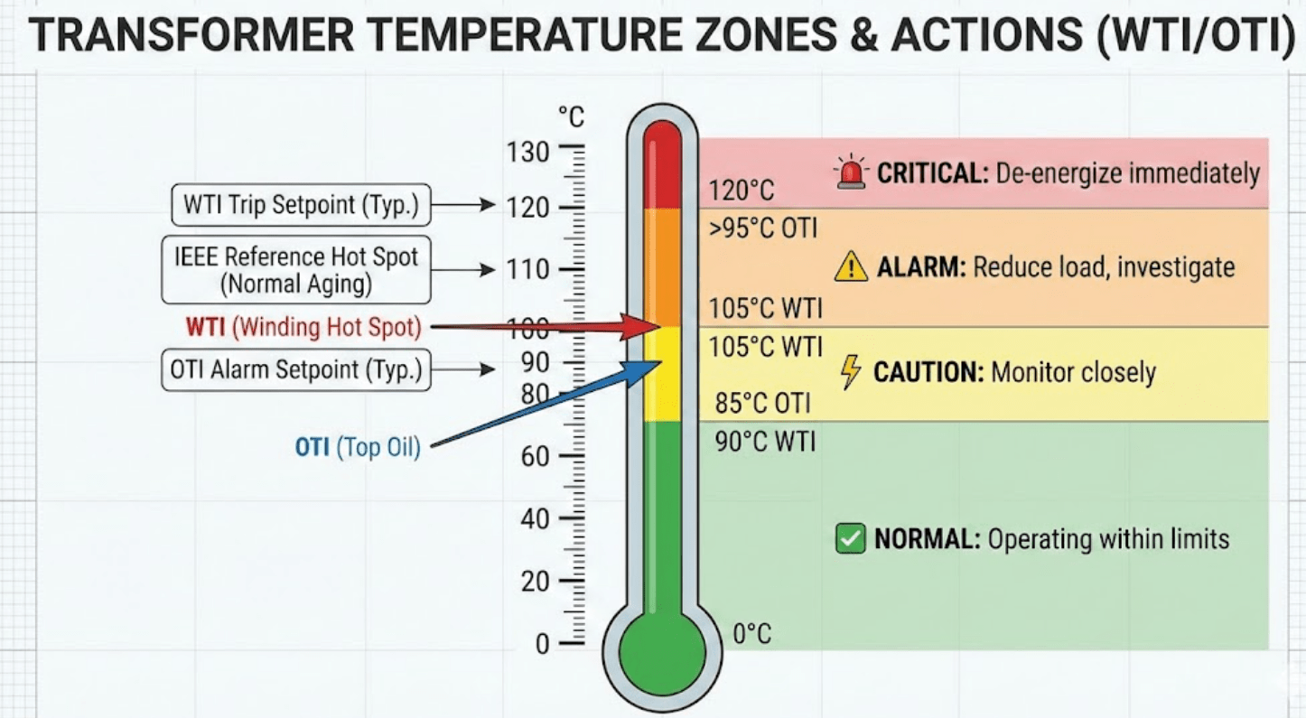
Visual representation of transformer temperature zones and alarm setpoints
8 Common Causes of Transformer Overheating
1. Overloading
Operating beyond rated kVA capacity causes excessive I²R losses in the windings. Copper losses increase
with the square of the current—200% load means 400% losses!
Check: Compare load current to nameplate rating. Use clamp meter if needed.
2. High Ambient Temperature
Transformers are typically rated at 30°C ambient. Per IEEE C57.91-2011: for each 1°C above 30°C, decrease
load by 1.5%. At 40°C ambient, de-rate the transformer to ~85% capacity.
3. Cooling System Failure
Failed fans, pumps, or blocked radiators drastically reduce heat dissipation capability.
- Check fan operation visually and electrically
- Verify oil pump flow (if OFAF/ODAF cooling)
- Inspect radiators for debris, bird nests, vegetation
- Confirm radiator valves are OPEN
4. Low Oil Level
Insufficient oil reduces thermal mass and disrupts natural convection. Oil should cover the windings
completely.
Check: MOG (Magnetic Oil Gauge) reading vs. ambient temperature chart on transformer.
5. Internal Faults
Turn-to-turn shorts, shorted laminations, or circulating currents create localized hot spots that may not
be reflected in OTI/WTI readings initially.
Indicators: Sudden temperature rise, DGA gases (acetylene, ethylene), humming noise
changes.
6. Harmonic Distortion
Non-linear loads (VFDs, rectifiers, computers) inject harmonics that cause additional eddy current and
stray losses in windings and core.
K-Factor: Transformers serving harmonic-rich loads should have appropriate K-rating
(K-4, K-13, K-20).
7. Unbalanced Loading
Unequal phase currents in 3-phase transformers cause uneven heating and increased losses. Aim for <10%
current unbalance.
8. Poor Ventilation
Outdoor units: Ensure minimum clearances per manufacturer (typically 1-2m around radiators).
Indoor units: Check ventilation system CFM requirements.
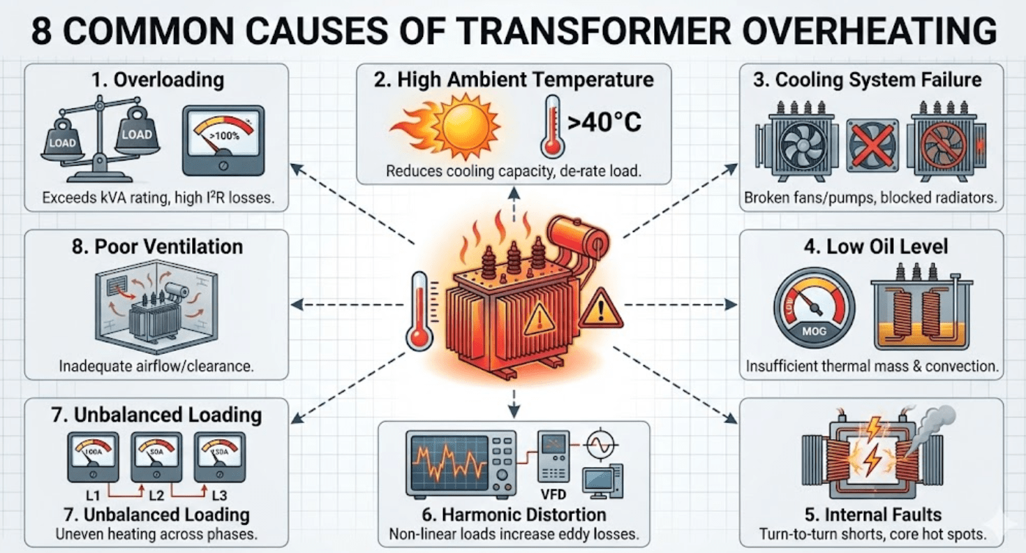
Infographic showing the 8 common causes of transformer overheating
Understanding OTI and WTI Readings
Oil Temperature Indicator (OTI)
The OTI measures top oil temperature directly using a sensing bulb immersed in a pocket
filled with transformer oil. It’s a straightforward measurement of the hottest oil in the system.
Winding Temperature Indicator (WTI)
The WTI provides a simulated hot spot temperature. It uses:
- A sensing bulb in the top oil (like OTI)
- A heater coil around the bulb fed by a CT proportional to load current
This adds a “thermal image” representing the winding-to-oil gradient. The WTI reading = Top Oil + (Load
Current Effect).
Typical Setpoints
| Function | OTI Setpoint | WTI Setpoint |
|---|---|---|
| Start Cooling Fans | 55-65°C | — |
| Start Oil Pumps | 65-75°C | — |
| High Temperature Alarm | 85-95°C | 95-105°C |
| Trip (De-energize) | 95-105°C | 110-120°C |
(many indicators have a drag pointer showing peak values). A high peak during unattended operation
indicates a problem worth investigating.
Temperature Troubleshooting Checklist
When Temperature Is High:
- Record current OTI and WTI readings
- Note ambient temperature
- Check load current vs. rated current
- Verify cooling fans are operating (visual + amp check)
- Verify oil pumps are operating (flow indicator, amp check)
- Check oil level on MOG
- Inspect radiators for blockages
- Verify radiator isolation valves are OPEN
- Listen for unusual noise (arcing, humming change)
- Check for visible oil leaks
- Review recent load history and ambient conditions
- Review DGA results if available
Infrared Thermography
Thermal imaging can reveal:
- Blocked radiator sections: Appear cooler than working sections
- Loose connections: Hot spots at bushings or tap changer terminals
- Tank hot spots: May indicate internal circulating currents
- Oil level issues: Visible thermal gradient at oil line
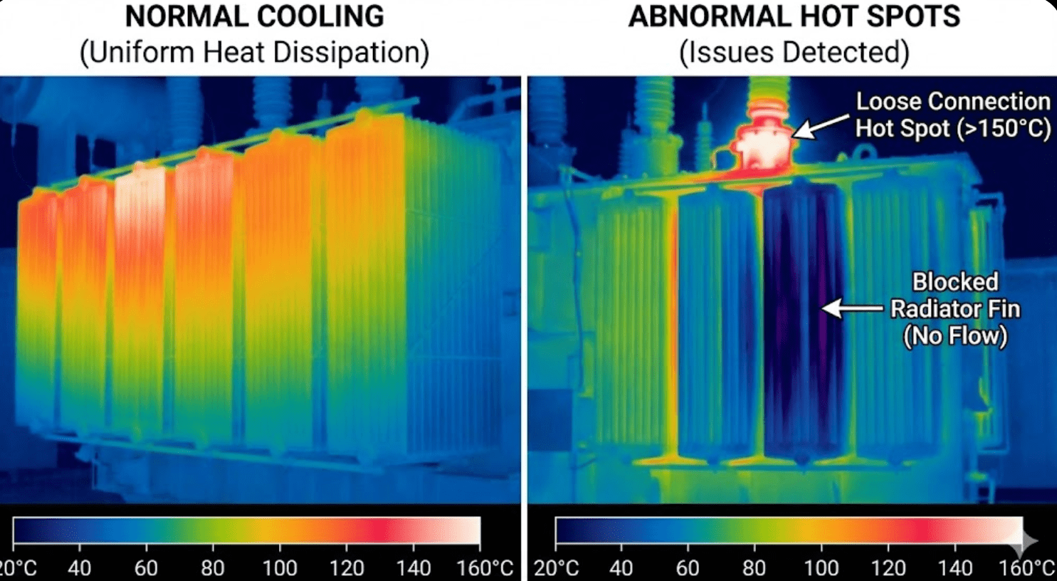
Infrared images showing normal vs. abnormal transformer thermal patterns
Emergency Response: High Temperature
🚨 If Temperature Exceeds Limits:
- Reduce Load Immediately — Transfer load to parallel units or shed non-critical
loads - Maximize Cooling — Manually start all cooling stages; open enclosure doors (if
outdoor) - Monitor Continuously — Take readings every 15 minutes
- Prepare for De-energization — If temperature continues rising, plan to
de-energize - Document Everything — Record times, readings, actions taken
- Notify — Alert supervision and arrange for DGA sampling once cooled
Temporary Cooling Measures
- Portable fans directed at radiators
- Water mist on radiators (use caution—avoid electrical components!)
- Shade structures to reduce solar heating
- Open enclosure/substation doors for airflow
radiator surfaces and only if safe to do so.
Loading Capacity vs. Ambient Temperature
Per IEEE C57.91, loading capability varies with ambient temperature:
| Ambient Temperature | Approximate Capacity | Notes |
|---|---|---|
| 20°C | ~110% | Cold weather allows +1%/°C below 30°C |
| 30°C (Reference) | 100% | Standard rating condition per IEEE C57.91 |
| 35°C | ~92.5% | 5°C × 1.5% = 7.5% derating |
| 40°C | ~85% | 10°C × 1.5% = 15% derating |
| 45°C | ~77.5% | 15°C × 1.5% = 22.5% derating |
| 50°C | ~70% | 20°C × 1.5% = 30% derating |
For precise loading guidance, IEEE C57.91 provides detailed tables and thermal models accounting for load
duration, cycling, and insulation class.
Frequently Asked Questions
How hot should a transformer feel to the touch?
A normally loaded transformer tank will be warm to hot. At rated load with 30°C ambient, the top of
the tank may reach 70-85°C—painfully hot but not an indication of a problem. Use temperature
indicators, not touch, for assessment. The bottom of the tank is typically cooler (50-60°C) due to
oil convection patterns.
Why is my transformer hot but OTI/WTI readings are normal?
Possible reasons: 1) The transformer is operating normally—transformers are designed to run warm; 2)
OTI/WTI calibration is off—compare with an IR thermometer; 3) Ambient temperature is high, making
the tank feel hotter while temperature rise remains within limits; 4) You’re touching a localized
hot spot (connection issue) not reflected in bulk oil temperature.
Can a transformer run 24/7 at 100% load?
Yes, if properly cooled and ambient temperatures don’t exceed design assumptions (typically 30°C
average, 40°C max). IEEE C57.91 assumes rated load can be sustained continuously at these
conditions. However, insulation life is finite—operating at slightly reduced loads (80-90%) extends
life significantly.
What is the “half-life rule” for insulation?
The Arrhenius rate law shows that insulation aging approximately doubles for every 6-8°C above the
reference hot spot (110°C). Conversely, operating 6-8°C cooler than rated can roughly double
insulation life. This is why reducing average load pays dividends in transformer longevity.
How often should temperature indicators be calibrated?
OTI and WTI should be tested/calibrated every 3-5 years, or after any indication of malfunction.
Testing involves applying known temperature sources and verifying pointer movement, mercury switch
contact closure, and dial accuracy. Many utilities include this in major outage maintenance
programs.
Preventive Measures
- Regular Inspections: Check cooling equipment monthly; clean radiators annually
- Load Monitoring: Track loading patterns; avoid sustained overloads
- Oil Quality: Maintain proper oil level and quality (BDV, moisture content)
- DGA Testing: Annual DGA detects thermal faults before temperature alarms
- Thermal Imaging: Annual IR survey identifies hot spots
- Cooling System Maintenance: Test fan/pump operation; replace failing units promptly
- Vegetation Control: Maintain clearances around outdoor transformers
Conclusion
Transformer temperature is a critical indicator of operational health. Understanding the difference
between OTI and WTI readings, knowing IEEE C57.91 limits, and following systematic troubleshooting
procedures enables rapid response to overheating events.
Remember: 110°C hot spot is the reference for normal aging. Operating significantly
above this sacrifices transformer life. When in doubt, reduce load and investigate.
Our field service team provides on-site diagnostics, thermal imaging, and cooling system maintenance.Contact Our Service Team
References