
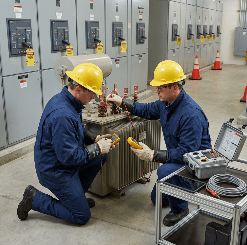
Last week, a utility company called me after a 500 kVA distribution transformer failed catastrophically, taking down
power to 200 homes. The investigation revealed they’d skipped routine testing for 3 years. The
failure cost them $85,000 in equipment replacement, $12,000 in emergency labor, and untold customer complaints.
After 15 years of testing transformers at Transformer4U, I’ve developed a systematic approach that
catches 95% of failures before they happen. This guide shows you exactly how to test a transformer
using basic tools (multimeter) and professional equipment (megger, TTR tester).
⚡ Quick Answer: How to Test a Transformer
To test a transformer, perform these essential checks in order:
- Visual inspection – Check for physical damage, oil leaks, overheating
- Winding resistance test – Verify continuity with multimeter (expect 0.1-100Ω depending on
size) - Insulation resistance test – Use megger, expect >1000 MΩ for new transformers, >100 MΩ for
in-service units - Transformer ratio test – Verify turns ratio matches nameplate (±0.5% tolerance)
- No-load and load loss tests – Measure efficiency and performance
⚠️ CRITICAL: Always de-energize and ground the transformer before
testing. Verify zero voltage with multimeter before touching any terminals.
Understanding Transformer Testing: Why It Matters
The Cost of Transformer Failure
Transformer failures are expensive and dangerous:
| Failure Type | Average Cost | Downtime | Safety Risk |
|---|---|---|---|
| Catastrophic failure (explosion) | $50k-500k | 24-72 hours | HIGH |
| Winding burnout | $15k-80k | 12-48 hours | MEDIUM |
| Insulation breakdown | $5k-30k | 8-24 hours | MEDIUM |
| Oil degradation | $2k-10k | 4-12 hours | LOW |
Regular testing prevents 90%+ of catastrophic failures by catching issues early.
When to Test a Transformer
| Transformer Type | Testing Frequency | Tests Required |
|---|---|---|
| Critical power (hospitals, data centers) | Every 6 months | All 8 tests |
| Industrial distribution | Annually | Tests 1-5 |
| Commercial building | Every 2-3 years | Tests 1-4 |
| Control transformers | Every 5 years or when suspect | Tests 1-3 |
Safety First: Pre-Test Procedures
⚡ DANGER: ELECTROCUTION HAZARD
Transformers can retain lethal voltage even after being disconnected from power
sources.
- De-energize both primary AND secondary sides
- Lock out/tag out (LOTO) all circuit breakers
- Wait 5 minutes minimum for capacitors to discharge
- Verify zero voltage with multimeter on ALL terminals
- Ground ALL windings with grounding cables before touching
- Never work alone on transformers >25 kVA
Required Personal Protective Equipment (PPE)
| PPE Item | Rating Required | Purpose |
|---|---|---|
| Insulated gloves | Class 00 (500V) minimum | Primary protection |
| Safety glasses | ANSI Z87.1 rated | Eye protection |
| Arc-rated clothing | ATPV 8 cal/cm² minimum | Arc flash protection |
| Multimeter | CAT III 1000V or CAT IV 600V | Safe voltage measurement |
Test 1: Visual Inspection (Always Start Here)
What to Inspect
External Components:
- ✅ Oil level (should be between min/max marks on sight glass)
- ✅ Oil color (should be clear/light amber, not dark or cloudy)
- ✅ Bushings (check for cracks, flashover marks, oil leaks)
- ✅ Tank condition (no bulges, rust, or deformation)
- ✅ Gaskets (no oil seepage or wetness)
- ✅ Terminations (tight, no discoloration or burning)
- ✅ Tap changer position (verify correct tap setting)
| Observation | Likely Problem | Action |
|---|---|---|
| Bulged tank | Internal pressure from gas buildup | DO NOT TEST – Replace immediately |
| Oil leaks | Gasket failure, weld cracks | Repair leak, test insulation |
| Dark/cloudy oil | Contamination, overheating | Oil filtration or replacement needed |
| Burning smell | Overheated winding or oil | EMERGENCY – Test all windings |
Test 2: Winding Resistance Test (Continuity)
Purpose
- Verify winding continuity (no open circuits)
- Detect shorted turns (lower resistance than expected)
- Establish baseline resistance for future comparison
Equipment Needed
Digital multimeter (resistance mode, 0.1Ω resolution) – Recommended: Fluke 117, Klein MM400
($50-200)
Step-by-Step Procedure
Step 1: Prepare Transformer
- De-energize transformer
- Disconnect ALL external connections (primary, secondary, ground)
- Verify zero voltage
- Short and ground all windings except test winding
Step 2: Measure Primary Winding Resistance
- Set DMM to resistance (Ω) mode
- Connect DMM leads to primary terminals (H1 to H2 for single-phase)
- Record resistance value
- For 3-phase: Measure H1-H2, H2-H3, H3-H1
Step 3: Measure Secondary Winding Resistance
- Connect DMM leads to secondary terminals (X1 to X2)
- Record resistance value
Typical Resistance Values
| Transformer Size | Primary Resistance | Secondary Resistance |
|---|---|---|
| 1 kVA (240/120V) | 5-15 Ω | 0.5-2 Ω |
| 10 kVA (480/120V) | 2-8 Ω | 0.1-0.5 Ω |
| 100 kVA (13.8kV/480V) | 50-200 Ω | 0.01-0.05 Ω |
| 500 kVA (13.8kV/480V) | 20-80 Ω | 0.002-0.01 Ω |
| 2500 kVA (13.8kV/480V) | 5-20 Ω | 0.0005-0.002 Ω |
⚠️ Note: ±10% from nameplate or baseline is acceptable. ±20%+ indicates fault.
Interpreting Results
| Test Result | Diagnosis | Action |
|---|---|---|
| Normal resistance (within ±10%) | ✅ Winding OK | Proceed to next test |
| Infinite resistance (OL) | ❌ Open winding | Replace transformer |
| Much lower resistance (>20% below) | ❌ Shorted turns | Replace transformer |
Test 3: Insulation Resistance Test (Megger Test)
Purpose
Test insulation quality between:
- Primary winding to ground
- Secondary winding to ground
- Primary to secondary windings (inter-winding)
This is the most important test for predicting transformer lifespan and safety.

Equipment Needed
Megohmmeter (Megger) – Recommended: Megger MIT1025, Fluke 1550C ($500-3,000)
Selecting Test Voltage
| Transformer Voltage | Recommended Megger Test Voltage |
|---|---|
| 120-600V | 500V or 1000V |
| 601V-5kV | 1000V or 2500V |
| 5kV-15kV | 2500V or 5000V |
Step-by-Step Procedure
Step 1: Prepare Transformer
- De-energize and verify zero voltage
- Disconnect ALL external connections
- Remove surge arresters if installed (they will cause low insulation readings)
- Ground tank/core
Step 2: Test Primary Winding to Ground
- Connect megger ground lead to transformer tank/frame
- Connect megger test lead to primary winding (H1 or all primary terminals shorted together)
- Short secondary winding to ground (X1-X2-ground)
- Apply test voltage for 60 seconds
- Record insulation resistance in MΩ (megohms)
Repeat for secondary to ground and primary to secondary tests.
Minimum Acceptable Insulation Resistance
IEEE Std 62.2-2004 Formula:
Minimum IR (MΩ) = (kV rating + 1) × 1000 MΩ
| Transformer Age | Minimum Acceptable IR | Condition |
|---|---|---|
| New (0-1 year) | ><10,000 MΩ | Excellent |
| 1-5 years | >5,000 MΩ | Good |
| 5-15 years | >1,000 MΩ | Fair |
| 15-30 years | >100 MΩ | Marginal |
<100 MΩ | FAIL | Requires drying or replacement |
<10 MΩ | CRITICAL FAIL | Do NOT energize |
Polarization Index (PI) Test
For more accurate assessment, perform a 10-minute insulation test:
- Measure IR at 1 minute = R1
- Measure IR at 10 minutes = R10
- Calculate: PI = R10 / R1
| PI Value | Insulation Condition | Recommendation |
|---|---|---|
| PI > 2.0 | ✅ Excellent | OK to energize |
| PI 1.5-2.0 | ✅ Good | OK to energize, monitor |
| PI 1.0-1.5 | ⚠️ Fair | Investigate, dry if possible |
| PI < 1.0 | ❌ Poor | Do not energize, requires drying |
Test 4: Transformer Turns Ratio (TTR) Test
Purpose
- Verify actual turns ratio matches nameplate specification
- Detect shorted turns (ratio will be incorrect)
- Confirm all tap positions are correct
Equipment Needed
Transformer Turns Ratio (TTR) Tester – Recommended: Vanguard ATRT-03, Megger TTR310 ($3,000-15,000)
Expected Turns Ratio
Turns Ratio (a) = Primary Voltage / Secondary Voltage
Examples:
- 13,800V / 480V = 28.75:1
- 480V / 120V = 4:1
- 240V / 24V = 10:1
Pass/Fail Criteria
IEEE C57.12.00 Standard: Tolerance ±0.5% of nameplate ratio
Example: 28.75:1 transformer
- Acceptable range: 28.61 to 28.89
- If measured ratio is 28.50 or 29.00 → FAIL
| Test Result | Diagnosis | Action |
|---|---|---|
| Ratio within ±0.5% | ✅ Pass | Transformer OK |
| Ratio -0.5% to -2% | ⚠️ Marginal | Investigate, possible shorted turns |
| Ratio >±2% | ❌ FAIL | Shorted turns – Replace transformer |
Test 8: Oil Dielectric Strength Test (BDV Test)
For oil-filled transformers only
Purpose
Measure oil’s ability to withstand electrical stress and detect moisture, particulates, or contamination.
BDV Test Pass/Fail Criteria
| Voltage Class | Minimum BDV (kV) | Condition | Action |
|---|---|---|---|
| <69 kV | >25 kV | Good | OK |
| <69 kV | 20-25 kV | Fair | Monitor |
| <69 kV | <20 kV | Poor | Oil filtration required |
Detailed guide: Transformer Oil BDV Test
Complete Guide
Complete Transformer Testing Flowchart
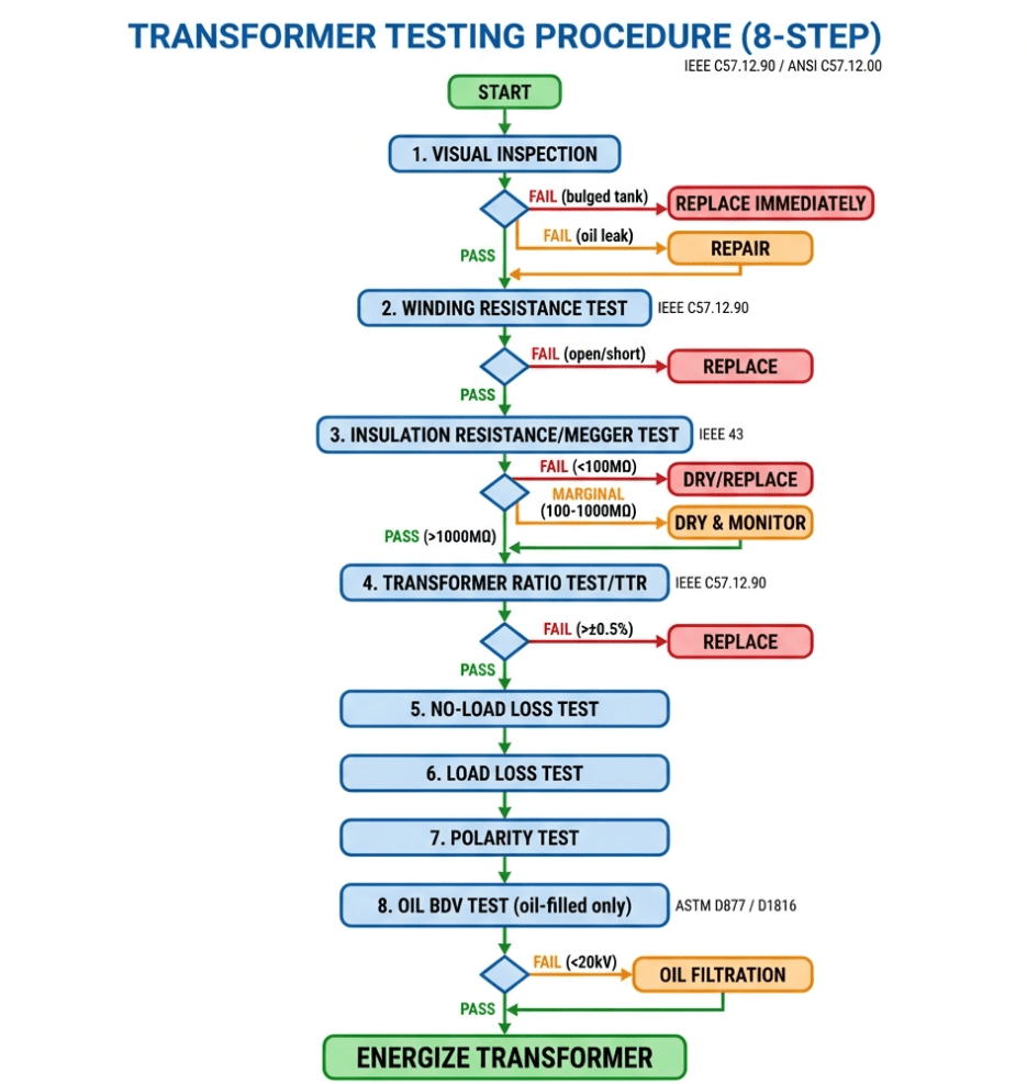
START
  ↓
[1. Visual Inspection]
  ↓
  ├─ FAIL (bulged tank, cracks) → REPLACE IMMEDIATELY
  ├─ FAIL (oil leak, dark oil) → Repair/Filter, then continue testing
  └─ PASS → Continue
        ↓
[2. Winding Resistance Test]
  ↓
  ├─ FAIL (open or shorted) → REPLACE
  └─ PASS → Continue
        ↓
[3. Insulation Resistance Test (Megger)]
  ↓
  ├─ FAIL (< 100 MΩ) → DRY or REPLACE ├─ MARGINAL (100-1000 MΩ) → Dry, retest, monitor closely └─ PASS (> 1000 MΩ) → Continue
        ↓
[4. Transformer Ratio Test (TTR)]
  ↓
  ├─ FAIL (>±0.5% error) → REPLACE
  └─ PASS → Continue
        ↓
[5. No-Load Loss Test]
  ↓
  ├─ FAIL (>±10% nameplate) → Investigate core damage
  └─ PASS → Continue
        ↓
[6. Load Loss Test]
  ↓
  ├─ FAIL (>±10% nameplate) → Investigate winding damage
  └─ PASS → Continue
        ↓
[7. Polarity Test]
  ↓
  ├─ FAIL (incorrect polarity) → Re-mark terminals
  └─ PASS → Continue
        ↓
[8. Oil BDV Test] (oil-filled only)
  ↓
  ├─ FAIL (< 20 kV) → OIL FILTRATION REQUIRED
  └─ PASS → TRANSFORMER OK
        ↓
[ENERGIZE TRANSFORMER]
Common Transformer Faults & Troubleshooting
Fault 1: Transformer Hums Loudly
Symptoms:
- Loud buzzing/humming noise (>60 dB)
- Vibration
- Normal voltage output
Possible Causes:
- Loose core laminations (most common)
- Overload (current > nameplate rating)
- Harmonic distortion from non-linear loads
Troubleshooting:
- Measure load current – if > nameplate, reduce load
- Measure voltage – should be ±5% of nameplate
- Check for loose mounting bolts – tighten
- If noise persists → Core damage, replace transformer
Fault 2: Low/No Output Voltage
Troubleshooting:
- Verify primary voltage present (use multimeter)
- Check tap changer position
- Perform winding resistance test:
- Infinite resistance = open winding → Replace
- Normal resistance = Check connections
FAQ: Transformer Testing
Can I test a transformer with just a multimeter?
Yes, for basic testing:
- ✅ Winding resistance test – Multimeter’s resistance mode
- ✅ Voltage verification – Multimeter’s AC voltage mode
- ❌ Insulation resistance – Requires megger (multimeter max ~40 MΩ, need >1000 MΩ)
- ❌ Transformer ratio – Requires specialized TTR tester
For small control transformers (<5 kVA), a multimeter is sufficient for basic troubleshooting.
For distribution transformers, you need professional equipment.
How do I test a transformer without power?
De-energized tests (no power required):
- Visual inspection ✓
- Winding resistance test ✓ (multimeter in resistance mode)
- Insulation resistance test ✓ (megger applies its own test voltage)
- Transformer ratio test ✓ (TTR tester applies low voltage ~10V)
You can fully diagnose most transformer faults without applying power using tests 1-4 above.
What does a bad transformer test like?
| Test | Bad Transformer Result | Indication |
|---|---|---|
| Winding resistance | Infinite (open) or very low (short) | Open or shorted winding |
| Insulation resistance | <100 MΩ | Moisture, contamination, insulation breakdown |
| Transformer ratio | >±0.5% error | Shorted turns in winding |
| Oil BDV | <20 kV | Contaminated oil |
If ANY of these fail, transformer is NOT safe to energize.
What is a good insulation resistance for a transformer?
| Insulation Resistance (MΩ) | Condition | Action |
|---|---|---|
| >10,000 MΩ | Excellent (new) | OK |
| 1,000-10,000 MΩ | Good | OK |
| 100-1,000 MΩ | Fair (older) | OK, monitor annually |
| 10-100 MΩ | Poor | Dry and retest, or plan replacement |
| <10 MΩ | FAIL | Do NOT energize – Replace |
Related Transformer Testing Guides
- CT Ratio Calculation & Selection Guide – Current transformer testing
- Distribution Transformer Losses Testing – Efficiency testing
- Transformer Oil BDV Testing – Oil quality analysis
- Transformer Oil Capacity Chart – Oil volume specifications
- 2500 kVA Transformer Specifications – Detailed transformer specs
Conclusion: Transformer Testing Best Practices
Key Takeaways:
- Always start with visual inspection – catches 50% of faults immediately
- Safety first – De-energize, lock out, verify zero voltage, ground all windings
- Three critical tests for basic health check:
- Winding resistance (continuity)
- Insulation resistance (safety)
- Transformer ratio (performance)
- Document everything – Create baseline for future trending
- Test regularly – Don’t wait for failure (costs 10x more than prevention)
References
- IEEE Std C57.12.00-2015 – General
Requirements for Liquid-Immersed Distribution, Power, and Regulating Transformers - IEEE Std C57.12.90-2015 – Test Code for
Liquid-Immersed Distribution, Power, and Regulating Transformers - IEEE Std 62.2-2004 – Guide for
Diagnostic Field Testing of Electric Power Apparatus - Transformer
Testing – Wikipedia - All About Circuits – Transformers – Educational resource
Written by Tan, Senior Transformer Technician at
Transformer4U with 15+ years of experience in transformer testing, commissioning, and failure analysis. Over
1,000 transformers tested across industrial, commercial, and utility applications.