
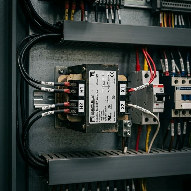
Last year, our export logistics team shipped a batch of 500 VA control transformers to a panel builder in Texas. Two weeks later, they emailed us a photo: a scorched transformer, a melted fuse block, and a very frustrated customer. The unit had been wired correctly — but the dual-voltage primary taps had been left in the factory-default 480V series configuration while installed on a 240V system. The core immediately saturated, drew 8× rated current, and cooked itself in under three minutes.
That photo is pinned above my desk. After 12 years building transformers at our factory, I have seen every wiring mistake imaginable. The fundamentals are straightforward — but the details matter enormously. This guide covers everything you need: control transformer wiring diagrams, terminal identification, complete sizing calculations, NEC code references, and the seven most costly mistakes we see from the field.
If you need background on how control transformers differ from power transformers, see our dry-type transformer overview. For three-phase installations, our 3-phase transformer bank wiring guide covers delta and wye configurations in detail. If you are sourcing a new unit, Transformer4U’s industrial control transformers are available from 50 VA to 5 kVA with factory-verified tap documentation included in every shipment.
📋 Table of Contents
- Terminal Identification: H1, H2, X1, X2 Explained
- Control Transformer Wiring Diagram (480V→120V)
- Dual-Voltage Primary Wiring (Series vs. Parallel)
- VA Sizing Calculator: Step-by-Step with Real Examples
- NEC 450.3(B) Fuse & Breaker Sizing Table
- Grounding Requirements (NEC 250.20)
- Step-by-Step Wiring Procedure
- 7 Wiring Mistakes That Destroy Transformers
- Troubleshooting: No Output / Low Voltage / Overheating
- FAQ
1. Terminal Identification: H1, H2, X1, X2 Explained
Every control transformer has four standard terminal markings defined by IEEE C57.12.90 and ANSI standards:
| Terminal | Winding | Voltage (typical) | Function | Wire Color (NFPA 79) |
|---|---|---|---|---|
| H1 | Primary | 480V or 240V | High-voltage input, line side | Black (or Red phase) |
| H2 | Primary | 480V or 240V | High-voltage input, line side | Black (or second phase) |
| H3, H4 | Primary (dual-V) | Tap junction | Jumper terminals for 240V vs 480V | Jumper wire |
| X1 | Secondary | 120V or 24V | Low-voltage output, hot side | Red (control hot) |
| X2 | Secondary | 120V or 24V | Low-voltage output, common/neutral | White (or Blue per NFPA 79) |
| X3 | Secondary (dual-V) | Mid-tap | Tap for dual-secondary voltage | Per manufacturer |
The polarity rule: H1 and X1 are always in-phase — both reach peak positive voltage at the same instant. This matters when paralleling two transformers or checking voltage relationships in complex control panels.
// Standard 480V → 120V single-secondary wiring (text diagram):
480V LINE ──[FUSE]──► H1 ┐
480V LINE ──────────► H2 ┘ [TRANSFORMER CORE]
X1 ──► [FUSE] ──► Control Circuit HOT
X2 ──────────────► Control Circuit COMMON
X2 ──────────────► Equipment Ground Bus ⏚
2. Control Transformer Wiring Diagram (480V → 120V)
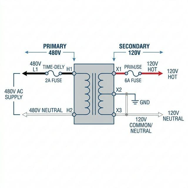
The diagram above shows the complete wiring for the most common industrial scenario: a 480V three-phase system powering a control transformer that supplies 120V to contactors, pilot lights, and a PLC input module. Key elements:
| Connection Point | Wire | NEC Requirement | Notes |
|---|---|---|---|
| 480V line → Primary fuse | 14 AWG min (125% FLA rule) | NEC 310, 450.3(B) | Fuse size = 125% × primary FLA; round up to std size |
| Primary fuse → H1 | Same gauge | NEC 310 | Black insulation per NFPA 79 for line-side 480V |
| Second 480V line → H2 | 14 AWG min | NEC 310 | Connect across two phases of 3-phase supply, or L1/L2 of single-phase |
| X1 → Secondary fuse | 14 AWG (typical for 120V/15A circuits) | NEC 450.3(B) | Fuse = 125% of secondary FLA |
| Secondary fuse → Control circuit | 14 or 16 AWG | NEC 725 (Class 1) | Red per NFPA 79 for control voltage hot |
| X2 → Common bus | 14 AWG | NEC 250.20 | White; also bonded to ground bus |
| X2 → Ground bus | Green/bare per NEC Table 250.102 | NEC 250.20, 250.30 | Mandatory when primary >150V to ground |
3. Dual-Voltage Primary Wiring: Series vs. Parallel
Most North American industrial control transformers are shipped from the factory with the primary wired for the higher voltage (480V) in series configuration. This is the most common source of field wiring errors — particularly when the transformer is installed on a 240V system without reconfiguring the jumpers.
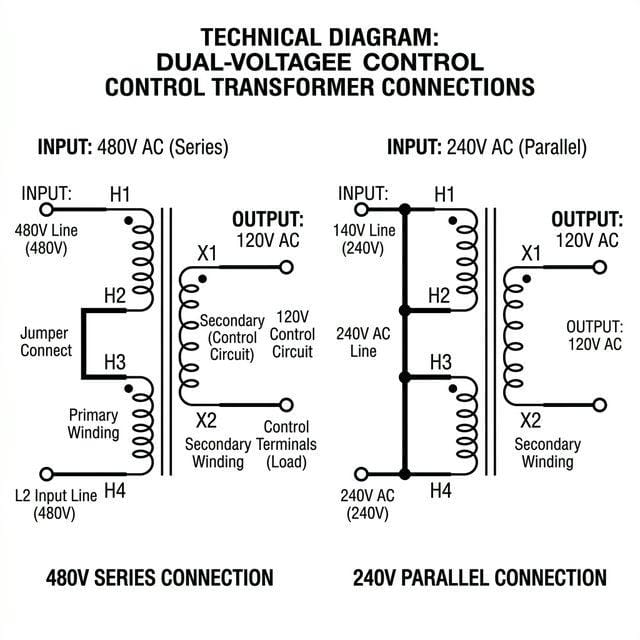
| Supply Voltage | Connection Type | Jumper Position | Power Terminals | Each Half-Winding Sees |
|---|---|---|---|---|
| 480V | Series (default) | H2 jumpered to H3 | H1 and H4 | 240V each (adds to 480V) |
| 240V | Parallel | H1→H3 jumper; H2→H4 jumper | H1/H3 and H2/H4 | 240V each (parallel = same V, more I) |
Wiring for 240V Single-Phase Systems (Residential & Light Commercial)
In residential and light commercial installations, control transformers are often fed from a 240V/120V split-phase service (two 120V legs, 240V line-to-line). The correct connection depends on your required output:
| Scenario | Primary Connection | Secondary Output | Note |
|---|---|---|---|
| 240V L-to-L → 120V output (most common) | H1 to L1 (hot leg 1); H2 to L2 (hot leg 2). Both lines are 120V to neutral, 240V between them. | X1–X2 = 120V | Do NOT connect H2 to neutral on a 240V L-to-L primary — you would apply only 120V to a 240V-rated primary. |
| 240V single-voltage unit → 120V output | H1 to L1, H2 to L2 (same as above) | X1–X2 = 120V | Single-voltage units have no H3/H4 taps — no configuration needed. |
| 240V dual-voltage unit on 240V supply | H1 jumpered to H3; H2 jumpered to H4; supply to H1/H3 and H2/H4 (parallel configuration) | X1–X2 = 120V | Factory ships wired for 480V (series). Must re-jumper for 240V before energizing. |
4. VA Sizing Calculator: Step-by-Step with Real Examples
Undersizing is the leading cause of control transformer failure in motor control centers. The key issue: most technicians calculate only sealed (steady-state) VA, ignoring the inrush current that magnetic loads draw during the first few AC cycles of energization. A contactor coil rated 20 VA sealed can draw 120–200 VA during the first 100 milliseconds.
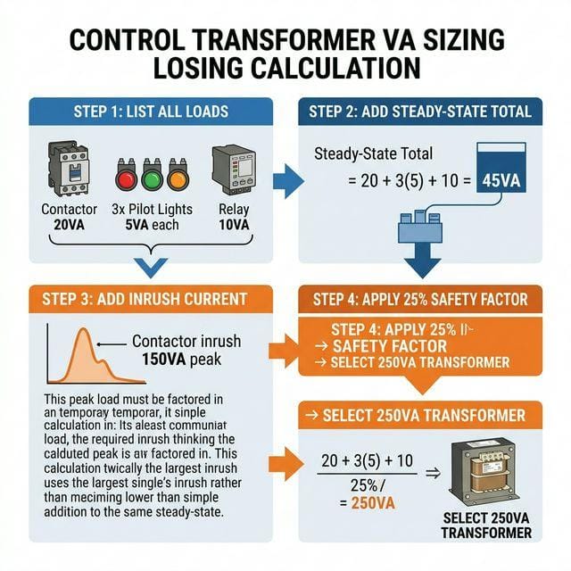
The 4-Step Sizing Method
Step 1 — List all loads and their VA ratings:
| Load Device | Quantity | Sealed VA (each) | Inrush VA (each) | Inrush Factor |
|---|---|---|---|---|
| NEMA Size 2 Contactor coil | 1 | 20 VA | 120 VA | 6× |
| Auxiliary relay coil | 2 | 10 VA | 60 VA | 6× |
| LED pilot lights | 3 | 5 VA | 5 VA | 1× (resistive) |
| Timer relay | 1 | 8 VA | 8 VA | 1× (solid state) |
| PLC input module (120V AC) | 1 | 25 VA | 25 VA | 1× (electronic) |
Step 2 — Calculate steady-state total:
Steady-State VA = (1×20) + (2×10) + (3×5) + (1×8) + (1×25) = 20 + 20 + 15 + 8 + 25 = 88 VA
Step 3 — Calculate peak inrush demand (worst-case simultaneous energization):
Inrush VA = (1×120) + (2×60) + (3×5) + (1×8) + (1×25) = 120 + 120 + 15 + 8 + 25 = 288 VA peak
Step 4 — Apply 20–25% safety factor and select standard size:
Minimum VA = 288 × 1.25 = 360 VA → Select 500 VA (next standard size above 360)
Standard Control Transformer Sizes
Available standard VA ratings (NEMA/UL): 50, 75, 100, 150, 200, 250, 350, 500, 750, 1000 VA. Always select the next size up from your minimum calculated requirement — never round down.
5. NEC 450.3(B) Fuse & Breaker Sizing Table
NEC Article 450.3(B) governs overcurrent protection for transformers rated 1,000V or less. The calculation is straightforward:
Primary FLA = VA ÷ Primary Voltage      (single-phase)

Primary Fuse = Primary FLA × 125% → round up to next standard size

Secondary FLA = VA ÷ Secondary Voltage

Secondary Fuse = Secondary FLA × 125% → round up to next standard size
Reference table for the most common 480V primary / 120V secondary configurations:
| Transformer VA | Primary FLA (480V) | Primary Fuse (125%) | Secondary FLA (120V) | Secondary Fuse (125%) | Fuse Class |
|---|---|---|---|---|---|
| 50 VA | 0.10 A | 0.15 A → 0.2 A | 0.42 A | 0.52 A → 0.6 A | Class CC |
| 75 VA | 0.16 A | 0.20 A → 0.25 A | 0.63 A | 0.79 A → 1 A | Class CC |
| 100 VA | 0.21 A | 0.26 A → 0.3 A | 0.83 A | 1.04 A → 1.25 A | Class CC |
| 150 VA | 0.31 A | 0.39 A → 0.5 A | 1.25 A | 1.56 A → 2 A | Class CC |
| 200 VA | 0.42 A | 0.52 A → 0.6 A | 1.67 A | 2.08 A → 2.5 A | Class CC |
| 250 VA | 0.52 A | 0.65 A → 0.8 A | 2.08 A | 2.60 A → 3 A | Class CC |
| 350 VA | 0.73 A | 0.91 A → 1 A | 2.92 A | 3.65 A → 4 A | Class CC |
| 500 VA | 1.04 A | 1.30 A → 1.5 A | 4.17 A | 5.21 A → 6 A | Class CC |
| 750 VA | 1.56 A | 1.95 A → 2 A | 6.25 A | 7.81 A → 8 A | Class CC or J |
| 1000 VA | 2.08 A | 2.60 A → 3 A | 8.33 A | 10.4 A → 10 A or 12 A | Class CC or J |
| 1500 VA | 3.13 A | 3.90 A → 4 A | 12.5 A | 15.6 A → 15 A | Class J |
| 2000 VA | 4.17 A | 5.21 A → 6 A | 16.7 A | 20.8 A → 20 A | Class J |
6. Grounding Requirements (NEC 250.20)
This is the section most often skipped during inspection — and the most dangerous to omit. NEC 250.20(B)(1) requires that one conductor of an AC system (50V–1000V) must be grounded when the system is derived from a transformer and the voltage to ground does not exceed 150V on the secondary side. A 480V→120V control transformer creates exactly this scenario: the 120V secondary is a separately derived system with 120V to ground (≤150V), so secondary grounding is mandatory. Skipping it is a code violation and a personnel safety hazard.
What Must Be Grounded
- X2 secondary terminal: Bond to the equipment grounding conductor. This establishes X2 as the grounded (neutral) conductor and sets the system’s voltage reference to ground.
- Transformer enclosure/frame: Bond to the panel’s equipment grounding bus regardless of secondary voltage. This protects personnel if a winding fault energizes the enclosure.
- Grounding electrode conductor: Per NEC 250.30(A), a separately derived system requires a connection to the building’s grounding electrode system — typically at the first disconnect means or at the transformer itself.
| Scenario | Secondary → 120V output | X2 Ground Bond Required? | NEC Reference |
|---|---|---|---|
| 480V primary → 120V secondary (most common industrial) | 120V ≤ 150V to ground | Yes — required | NEC 250.20(B)(1) |
| 240V primary → 120V secondary (light commercial) | 120V ≤ 150V to ground | Yes — required | NEC 250.20(B)(1) |
| 480V primary → 24V secondary (PLC/automation) | 24V ≤ 150V to ground | Yes — required | NEC 250.20(B)(1) |
| Any primary → secondary >150V to ground (uncommon for control transformers) | >150V to ground | Not required by NEC 250.20(B)(1) — but enclosure must still be grounded | NEC 250.134 |
| Transformer in wet/damp location, any secondary voltage | Any | Yes — required regardless | NEC 250.20(B)(2) |
| Transformer enclosure/frame (all cases, no exception) | — | Yes — always | NEC 250.134 |
7. Step-by-Step Wiring Procedure
This is the procedure our factory’s commissioning team follows when wiring control transformers in panel assemblies. Takes approximately 30–45 minutes per transformer for a careful first-time installation.
- Apply Lockout/Tagout — verify zero energy. De-energize the panel. Apply your personal LOTO device. Use a calibrated CAT III or CAT IV multimeter to verify zero volts between all supply conductors and between each conductor and ground. Transformers can retain dangerous induced voltages even after the upstream breaker opens — always verify with a meter, never assume.
- Read the nameplate completely. Note: primary voltage(s), secondary voltage(s), VA rating, Hz, duty cycle, insulation class, and the wiring diagram on the nameplate. For dual-voltage units, find the tap configuration table. Confirm the current tap position matches your supply voltage. If not — stop and reconfigure before going further.
- Reconfigure dual-voltage taps if needed. For 480V operation: H2 jumpered to H3, supply to H1 and H4. For 240V operation: H1 jumpered to H3, H2 jumpered to H4, supply to H1/H3 and H2/H4 (see Section 3 diagram). Use appropriately rated jumper wire and torque the terminal screws.
- Install the primary fuse holder and fuse. Use the NEC 450.3(B) table in Section 5. Mount the fuse holder on the line side (before H1). Class CC fuse holders (Bussmann CH or equivalent) are standard for 600V control circuits.
- Wire the primary side (H1 and H2). Route 14 AWG THHN from the upstream 480V supply through the fuse to H1. Connect the second 480V phase directly to H2. Torque terminal screws to the manufacturer’s specification — typically 12–15 in-lb for #14 AWG on screw-type terminals. Under-torqued terminals are a leading cause of thermal failures in industrial panels.
- Install the secondary fuse holder and fuse. Mount on the X1 output side. Use the secondary fuse size from Section 5 for your transformer’s VA rating.
- Wire the secondary X1 (hot) conductor. From X1, through the secondary fuse, to your control circuit. Use 14 or 16 AWG THHN, red insulation per NFPA 79 machine wiring standard for control voltage hot conductors.
- Wire the X2 (common/neutral) conductor. From X2 to the common bus bar. White insulation. This conductor serves as the return path for all 120V control circuits.
- Install the X2 ground bond (mandatory). Run a separate green or bare conductor from X2 to the equipment grounding bus (the green bus bar bonded to the panel enclosure). Size per NEC Table 250.102(C)(1) based on secondary conductor size — for 14 AWG secondary conductors, a 14 AWG or larger ground wire is acceptable, though many engineers run 12 AWG for reliability margin.
- Bond the transformer enclosure to ground. A separate ground wire from the transformer’s mounting bracket or enclosure lug to the panel ground bus. This is a separate connection from the X2 ground bond, though they connect to the same bus.
- Complete final connections and verify torque on all terminals. Go through every terminal — H1, H2, X1, X2, fuse terminals, and ground connections — and verify proper torque. A torque screwdriver is not optional on IEC/UL-listed equipment where torque specifications are provided.
- Energize and verify secondary voltage. Remove LOTO, re-energize the supply. Measure X1 to X2 under no load — should read within ±5% of nameplate (114–126V for a 120V secondary). Then connect the control circuit and re-measure under load. A voltage drop greater than 5% under load suggests the transformer is undersized for the actual load.
8. Seven Wiring Mistakes That Destroy Control Transformers
| # | Mistake | What Happens | How to Prevent |
|---|---|---|---|
| 1 | Wrong tap setting (dual-voltage units) | 480V transformer wired for 480V installed on 240V: output drops to ~60V, transformer runs hot. Reverse: 480V on 240V-wired unit → core saturates in <10 seconds, winding burns. | Read nameplate wiring diagram. Check jumper between H2 and H3 before energizing. Stamp or label the tap setting on the panel door. |
| 2 | Omitting the X2 ground bond | Secondary circuit floats to undefined voltage relative to ground. A winding fault can energize control circuit conductors to 240V or 480V without tripping any overcurrent device. | Always bond X2 to ground bus per NEC 250.20. It’s not optional on any 240V or 480V fed system. |
| 3 | Sizing for steady-state VA only (ignoring inrush) | Contactor inrush causes voltage sag below 85% on energization → contactors fail to pull in or drop out immediately. Transformer runs overloaded, overheats over months. | Use the 4-step sizing method (Section 4). Add inrush VA of all inductive loads to steady-state before applying safety factor. |
| 4 | Undersized or missing primary fuse | Winding-to-winding or winding-to-core fault draws high fault current without clearing. Transformer burns before upstream breaker trips (breakers are not rated to protect transformer windings). | Always install a dedicated primary fuse per NEC 450.3(B). Do not rely solely on an upstream breaker for transformer protection. |
| 5 | Loose terminal connections | High-resistance joint heats under load. Insulation chars, voltage drop increases, eventually arc-flash event. The failure is gradual and often undetected until charring is visible. | Torque all screws to spec. For panels that vibrate (motor control, compressor rooms), use spring-coil terminals or re-verify torque on annual inspection. |
| 6 | Exceeding secondary fuse size (using “whatever fits”) | Oversized secondary fuse allows sustained overload that damages control wiring insulation before the fuse clears. Creates fire risk in the control panel. | Calculate secondary fuse per NEC 450.3(B). Use Class CC fuses for control transformer circuits — they provide proper current-limiting characteristics. |
| 7 | Connecting 3-phase supply to both H1 and H2 without checking phase-to-phase voltage | On 480V delta systems, line-to-line is 480V as expected. But on 480Y/277V systems, connecting across two phases still gives 480V L-L — so this is usually fine. The error occurs when someone connects H1/H2 to L1 and neutral on a 480Y system, giving only 277V to the primary — output drops to ~69V instead of 120V. | Verify that the two conductors feeding H1 and H2 produce the rated primary voltage (measure L-to-L, not L-to-N) before energizing. |
9. Troubleshooting: No Output / Low Voltage / Overheating
| Symptom | Most Likely Cause | Diagnostic Step | Fix |
|---|---|---|---|
| No secondary output voltage | Blown primary fuse; open primary winding; wrong tap position giving output at wrong terminals | 1. Check primary fuse continuity. 2. Measure primary voltage at H1–H2. 3. Check secondary at X1–X2 with no load. | Replace blown fuse. If fuse blows again immediately: check for short in control wiring before re-energizing. If primary voltage OK but no secondary output: test winding continuity (ohmmeter, both windings should read low resistance). |
| Secondary voltage low under no-load | Wrong tap (primary on 240V tap with actual 480V supply); shorted turns in secondary winding | Measure primary voltage at H1–H2. Compare to nameplate. Check no-load secondary against nameplate. | Reconfigure taps to match supply voltage. If no-load voltage is correct but drops under load: transformer is undersized — install larger VA unit. |
| Secondary voltage drops >5% under load | Transformer undersized for actual VA demand (inrush not accounted for); loose terminal causing voltage drop | Measure secondary voltage under worst-case load condition (all contactors simultaneously energized). Measure current at X1 conductor. | If current exceeds rated secondary FLA: replace with larger VA transformer. If current is within rating but voltage still drops: inspect and re-torque all terminal connections. |
| Transformer overheats (surface >60°C above ambient) | Overloaded (inrush not calculated); wrong tap (secondary working harder than designed); inadequate ventilation; ambient temperature >40°C | Use IR thermometer or thermal camera. Check surface temperature at steady-state load. Verify airflow around unit is unobstructed. | Verify VA demand vs. rating. Check tap setting. Re-calculate with temperature derating if ambient >40°C (derate 2–3% per °C above 40°C for most Class B/F insulation). Replace with larger unit or add ventilation. |
| Transformer hums loudly | Primary voltage exceeds nameplate by >5%; loose mounting bolts or core stack; mechanical resonance with panel enclosure | Measure primary voltage. Should be within ±5% of nameplate. Verify mounting bolts are tight. | If primary voltage is high: notify utility or install a buck-boost transformer upstream. Tighten all four mounting bolts. Add vibration-dampening mounts if enclosure resonates. |
| Primary fuse blows on energization | Fuse undersized for inrush; transformer energized during a fault; internal transformer fault | Check fuse type (must be time-delay for inductive primary inrush). Disconnect all secondary loads and try energizing with secondary open-circuit. | Replace instantaneous fuse with time-delay type (Class CC, time-delay rated). If fuse still blows with no secondary load: transformer has internal fault and must be replaced. |
10. Frequently Asked Questions
How do I wire a 480V to 120V control transformer?
Connect the 480V phase conductor to H1 through a primary fuse (sized at 125% of primary FLA per NEC 450.3(B)), and the second 480V phase to H2. On the secondary side, connect X1 through a secondary fuse to your 120V control circuit hot conductor, and X2 to the common bus. Bond X2 to the equipment ground bus using a separate conductor per NEC 250.20. For a 500 VA unit: primary fuse = 1.5A, secondary fuse = 6A. See the complete step-by-step procedure in Section 7.
What are H1, H2, X1, X2 terminals on a control transformer?
H1 and H2 are the primary (high-voltage) winding terminals. X1 and X2 are the secondary (low-voltage output) terminals. Per IEEE C57.12.90, H1 and X1 share the same instantaneous polarity — both are positive simultaneously. Dual-voltage transformers add H3/H4 (primary taps) and sometimes X3 (secondary tap). Never assume terminal position from physical location — always follow the nameplate wiring diagram.
What size fuse does a 500 VA control transformer need?
Per NEC 450.3(B) with 480V primary and 120V secondary: Primary fuse = 1.5A or 2A (Class CC, time-delay); Secondary fuse = 6A (Class CC). The full calculation: Primary FLA = 500 ÷ 480 = 1.04A × 1.25 = 1.3A → round up to 1.5A standard. Secondary FLA = 500 ÷ 120 = 4.17A × 1.25 = 5.21A → round up to 6A. Use time-delay Class CC fuses — a transformer’s magnetizing inrush current (typically 8–12× rated for the first 1–3 cycles on energization) will nuisance-trip instantaneous fuses even with no load connected. This magnetizing inrush is separate from the load-side contactor inrush discussed in Section 4.
Does a control transformer need to be grounded?
Yes, for virtually all control transformer installations. NEC 250.20(B)(1) requires bonding one secondary conductor (X2) to the equipment grounding bus when the transformer creates a separately derived system with secondary voltage to ground ≤150V — which covers every standard 480V→120V and 480V→24V control transformer. The transformer enclosure must also be grounded per NEC 250.134, regardless of secondary voltage. Both connections are always required on industrial control panels and are specifically checked during inspection.
How do I size a control transformer for a motor starter?
Use the 4-step method: (1) List all loads with both sealed and inrush VA. (2) Sum steady-state VA. (3) Add the peak inrush VA from all inductive loads that energize simultaneously (contactor coil inrush is typically 6–10× sealed VA for AC coils). (4) Multiply by 1.25 safety factor and select the next standard size. Simple example (single starter, minimal loads): 20VA contactor sealed + 10VA relay + 15VA lights + 120VA contactor inrush = 165VA × 1.25 = 206VA → select a 250 VA transformer. For a more realistic panel with multiple simultaneous inrush loads, see the full worked example in Section 4, which yields 500 VA for the same base loads with three contactors.
Why does my control transformer vibrate and hum after installation?
Some 60Hz hum (120Hz mechanical vibration from magnetostriction) is normal and unavoidable. Excessive noise has three common causes: (1) Primary voltage too high — measure V at H1–H2; anything more than +5% of nameplate rating causes the core to operate in saturation on each half-cycle, dramatically increasing noise; (2) Loose mounting — tighten all four mounting bolts and check that the core stack is tight internally; (3) Mechanical resonance — the panel enclosure or mounting surface amplifies vibration; add rubber isolation mounts between the transformer feet and the panel subplate.
Need a control transformer for your motor control center or machine panel?
At Transformer4U, we manufacture industrial control transformers from 50 VA to 5 kVA — 480V/240V dual-primary, 120V/24V secondary, pre-wired taps, UL/CE listed. Our engineering team can help you size and configure the right unit for your application.
Key Takeaways
- H1/H2 = primary (high-voltage) terminals; X1/X2 = secondary (low-voltage) terminals. H1 and X1 share the same instantaneous polarity per IEEE convention.
- Always verify dual-voltage tap position before energizing — factory default is usually 480V. Installing on a 240V system without reconfiguring gives wrong output and causes overheating.
- Size VA for simultaneous worst-case inrush, not just steady-state sealed current. A contactor coil’s inrush is 6–10× its sealed VA rating.
- Primary fuse = 125% × primary FLA per NEC 450.3(B). For 500 VA at 480V: 1.5A primary fuse, 6A secondary fuse. Use time-delay Class CC fuses.
- Bond X2 to the equipment ground bus — mandatory per NEC 250.20 on all 240V and 480V fed systems. Separately bond the transformer enclosure.
- Torque all terminal screws to specification. Loose connections are the leading cause of thermal failures in industrial control transformers.
- Secondary voltage should read within ±5% of nameplate under full load. A sag over 5% means the transformer is undersized.
Related Articles
- 3-Phase Transformer Bank Wiring: Delta, Wye & 6 Mistakes to Avoid
- How to Test a Transformer with a Multimeter (Step-by-Step)
- Dry-Type Transformer: Complete Selection Guide
- Transformer Sizing Guide: How to Choose the Right kVA
- Transformer Noise Level Chart by kVA
- Toroidal Transformer: Why It Outperforms EI Core
- Contact Our Engineering Team
About the author: Tan is a transformer engineer at Transformer4U, a manufacturer of toroidal, EI, dry-type, and oil-immersed transformers with over 12 years of production and commissioning experience. He has wired and tested thousands of transformer installations for industrial clients across North America, Europe, and Southeast Asia.