
Last Updated: February 3, 2026 | Written by Tan @ Transformer4U
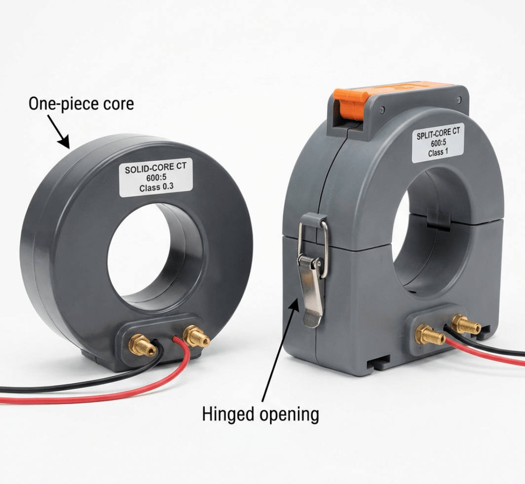
Solid-core (left) and split-core (right) current transformers – understanding the core difference for optimal CT selection
During a recent factory installation, a facility manager asked: “Why can’t I just measure 500A current directly with
a standard meter?” This common question highlights a critical misunderstanding about electrical measurement. After
15 years manufacturing transformers at Transformer4U, I can tell you that core current
transformers (CTs) are essential safety devices that step down dangerous high currents to safe
measurable levels — and choosing between solid-core and split-core designs can dramatically impact installation cost
and accuracy.
⚡ Quick Answer
A core current transformer (CT) safely measures high AC currents by using electromagnetic
induction to step down primary current (e.g., 500A) to a proportional secondary current (e.g., 5A or 1A). The
“core” refers to the magnetic core material that transfers energy between primary and secondary windings.
Solid-core CTs offer higher accuracy but require circuit disconnection for installation, while
split-core CTs allow easy retrofit installation by opening the hinged core around existing
conductors.
Learn more about how transformers work and transformer core types.
What is a Core Current Transformer?
A current transformer (CT) is an instrument transformer that reduces high primary currents to lower,
standardized secondary currents for safe measurement and protection applications. The term “core”
specifically refers to:
- The magnetic core material (typically silicon steel or ferrite) that forms the CT’s magnetic
circuit - The core type/configuration (solid-core vs. split-core vs. window-type)
Key Functions of Current Transformers
| Primary Function | How It Works | Benefits |
|---|---|---|
| Current Measurement | Steps down high current (100-1000A+) to 5A or 1A | Safe monitoring without direct exposure |
| Electrical Isolation | Magnetic coupling (no electrical connection) | Protects personnel and instruments |
| Power Metering | Enables accurate energy consumption measurement | Billing, load monitoring, efficiency tracking |
| Protection | Feeds protective relays for fault detection | Overcurrent/short circuit protection |
⚠️ Critical Safety Note: Never open-circuit a CT secondary while the primary
is energized. This creates dangerously high voltages (thousands of volts) that can damage equipment and injure
personnel.
How Core Current Transformers Work: The Physics
Basic Working Principle
Current transformers operate on electromagnetic induction — the same principle as power
transformers, but optimized for current measurement rather than voltage transformation.
Step-by-Step Process:
- Primary Current Flows Through Conductor – The primary conductor (carrying the current to be
measured) passes through the CT core. In many CTs, this conductor acts as a single-turn primary winding. - Magnetic Field Generation – The alternating current (AC) in the primary creates a time-varying
magnetic field around the conductor. - Magnetic Core Concentrates Flux – The magnetic core (made of high-permeability silicon steel)
concentrates and guides the magnetic flux through the secondary winding. - Secondary Current Induction – The changing magnetic flux cuts through the multi-turn secondary
winding, inducing a proportional voltage that drives current through the connected burden (measuring device or
relay). - Current Transformation – The CT’s turns ratio determines the relationship between primary and
secondary currents.
Current Transformation Ratio
The fundamental relationship is:
I_primary / I_secondary = N_secondary / N_primary
Practical Example:
CT Ratio: 600:5
Primary Current: 600A
Secondary Turns: 120 turns
Primary Turns: 1 turn (conductor through core)

Secondary Current = (600A × 1) / 120 = 5A
Common CT Ratios
| Primary Current | Secondary Current | CT Ratio | Typical Application |
|---|---|---|---|
| 100A | 5A | 100:5 (20:1) | Small motors, panels |
| 200A | 5A | 200:5 (40:1) | Distribution panels |
| 600A | 5A | 600:5 (120:1) | Industrial feeders |
| 1000A | 5A | 1000:5 (200:1) | Large transformers |
Core Types: Solid-Core vs. Split-Core Current Transformers
The choice between solid-core and split-core designs significantly impacts installation, accuracy, and cost.
Solid-Core Current Transformers
Construction: One-piece magnetic core (no separable parts), primary conductor must be threaded
through the core opening.
✅ Advantages:
- Higher Accuracy: Typically Class 0.2-0.5 (±0.2-0.5% error)
- Better Phase Angle: <15 minutes at rated current
- Lower Cost: Simpler manufacturing
- Higher Reliability: One-piece core, no hinges to degrade
❌ Disadvantages:
- Installation requires disconnecting primary conductor
- Circuit must be de-energized (downtime required)
- Not retrofit-friendly for existing installations
- Higher labor cost due to installation time
Split-Core Current Transformers
Construction: Two-piece hinged magnetic core, can be opened and closed around existing conductors,
secured with bolt/latch mechanism.
✅ Advantages:
- Easy Installation: No circuit downtime required
- Retrofit-Friendly: Install on energized circuits (with proper safety procedures)
- One-Handed Operation: Modern designs allow glove-friendly installation
- Lower Labor Cost: Faster installation = lower cost
❌ Disadvantages:
- Lower accuracy: Typically Class 1-3 (±1-3% error)
- Air gap at core joint introduces measurement errors
- Larger phase angle error (30-60 minutes)
- Higher initial cost (complex manufacturing)
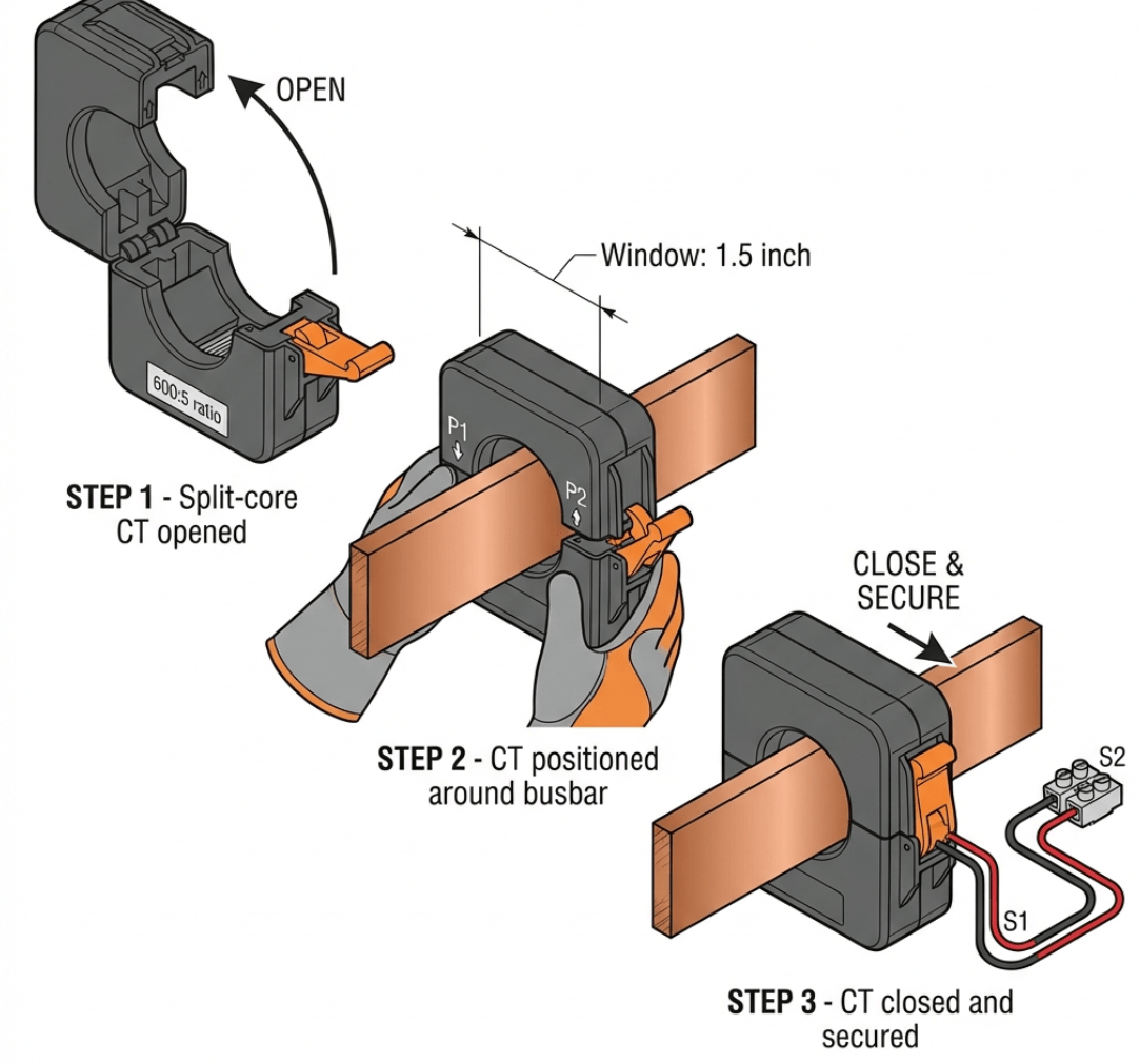
Split-core CT installation: OPEN → POSITION → CLOSE & SECURE
Core Type Comparison Table
| Feature | Solid-Core CT | Split-Core CT |
|---|---|---|
| Accuracy Class | 0.2-0.5 (±0.2-0.5%) | 1-3 (±1-3%) |
| Phase Angle Error | <15′ (minutes) | 30′-60′ |
| Installation Time | 30-60 min (circuit down) | 5-10 min (live) |
| Reliability | Excellent (one-piece core) | Good (hinge wear over time) |
| Retrofit Capability | Poor (requires de-energization) | Excellent (live installation) |
| Revenue Metering | ✅ Yes (IEEE C57.13) | ❌ No (insufficient accuracy) |
CT Accuracy Classes and Standards
IEEE C57.13 Standard (North America)
Metering Accuracy Classes:
| Class | Maximum Error | Phase Angle | Application |
|---|---|---|---|
| 0.15 | ±0.15% | ±5 minutes | Precision laboratory |
| 0.3 | ±0.3% | ±15 minutes | Revenue metering |
| 0.6 | ±0.6% | ±30 minutes | Submetering |
| 1.2 | ±1.2% | ±60 minutes | Energy management |
IEC 61869 Standard (International)
Metering Classes: 0.2, 0.2S, 0.5, 0.5S, 1, 3, 5
Protection Classes: 5P, 10P (P = Protection), 5PR, 10PR (R = Remanence, low residual magnetism)
How to Select the Right Core Current Transformer
Selection Criteria
1. Determine Primary Current
- Measure or calculate maximum expected current
- Add 20-30% safety margin
- Example: 400A max load → Select CT rated for 500A primary
2. Choose Secondary Current
- 5A secondary: North American standard, more common
- 1A secondary: European/Asian standard, lower burden
3. Determine Accuracy Requirement
- Revenue metering → Class 0.3 or better
- Energy management → Class 0.6-1.2
- Protection relaying → 5P/10P or C-class
- Temporary monitoring → Class 3 acceptable
4. Installation Method
- New installation + accessible wiring → Solid-core
- Retrofit/energized circuit → Split-core
5. Burden Calculation
The “burden” is the total load on the CT secondary, measured in VA or ohms.
Burden = Meter burden + Wire resistance + Relay burden
Example Calculation:
CT: 600:5, Class 0.3, Rated burden 2.5VA
Meter burden: 0.5VA
Wire: #14 AWG, 50 feet total = 0.25Ω
Relay burden: 1.0VA

Wire burden (VA) = I² × R = 5² × 0.25 = 6.25VA
Total burden = 0.5 + 6.25 + 1.0 = 7.75VA

⚠️ PROBLEM: 7.75VA > 2.5VA rated burden
Solution: Use larger wire (#12 AWG) or select CT with higher burden rating (e.g., B-4.0 = 4VA)
Installation Best Practices
Split-Core CT Installation
Step-by-Step:
- Safety Assessment – Qualified personnel, PPE required (NFPA 70E)
- Open Hinged Core – Release latch/bolt
- Position Around Conductor – Correct orientation (polarity marks P1/P2)
- Close and Secure Core – Tighten to specified torque
- Wire Secondary – Use shielded cable if >50ft
- Verify Installation – Secondary current matches expected ratio
⚠️ From Factory Experience: We’ve seen countless installation errors. The
most common: reversed polarity (protection relays trip unexpectedly), loose core
closure (10-30% measurement error), and excessive burden (CT saturates, inaccurate
readings).
Common Applications
1. Power Metering and Energy Management
- CT Type: Solid-core Class 0.3 (revenue) or split-core Class 1 (sub-metering)
- Typical Ratios: 100:5, 200:5, 400:5
2. Motor Protection
- CT Type: Solid-core Class 5P or split-core for retrofit
- Protection: Thermal overload relays, motor protection relays
3. Harmonic Monitoring
- CT Type: Wide-band CTs (response to 5kHz)
- Applications: Power quality analyzers
Frequently Asked Questions
What’s the difference between solid-core and split-core current transformers?
Solid-core CTs have a one-piece magnetic core requiring the primary conductor to be threaded through
during installation. They offer higher accuracy (0.2-0.5% error) but require circuit
deenergization for installation.
Split-core CTs feature a hinged core that opens and closes around existing conductors, allowing
retrofit installation on energized circuits (with proper safety procedures). They typically have
lower accuracy (1-3% error) but drastically reduce installation time and cost.
Choose solid-core for: Revenue metering, new installations, applications requiring <0.5%
accuracy
Choose split-core for: Retrofits, energy audits, non-billing applications, temporary monitoring
Can I use a current transformer for DC current measurement?
No, standard current transformers only work with AC (alternating current). CTs rely
on electromagnetic induction from a changing magnetic field. DC current creates a constant magnetic
field with no flux change, so no secondary current is induced.
For DC measurement, use Hall Effect sensors, Rogowski coils with integrators, or shunt resistors.
What happens if a CT secondary is open-circuited?
Extremely dangerous! An open-circuited CT can generate thousands of volts at the
secondary terminals because primary current still flows (CT has minimal impedance effect) with no secondary current
to oppose the magnetic flux. Core saturates, inducing very high voltage.
Consequences:
- ⚡ High voltage can electrocute personnel
- 🔥 Insulation breakdown and fire hazard
- 💥 CT damage (insulation failure)
- 📟 Connected meter/relay destruction
Prevention: Always short CT secondary terminals during installation/removal, use shorting blocks
when disconnecting metering equipment.
How do I determine the correct CT ratio for my application?
Step-by-Step CT Ratio Selection:
- Determine Maximum Primary Current
Example: 400A motor full-load current
Add 20-30% margin: 400A × 1.25 = 500A - Select Standard CT Ratio
Common ratios: 100:5, 200:5, 400:5, 600:5, 800:5, 1000:5
Choose ratio ≥ calculated max current
Selection: 600:5 CT (covers 500A + margin) - Verify Meter/Relay Compatibility
Most meters/relays designed for 5A or 1A input - Verify Burden Capacity
Calculate total burden (meter + wire + relay)
Ensure CT burden rating > total burden
Can I install split-core CTs on energized circuits?
Yes, but only with proper safety procedures and qualified personnel:
Safety Requirements (NFPA 70E):
- ✅ Arc-rated PPE (minimum 8 cal/cm²)
- ✅ Insulated gloves rated for system voltage
- ✅ Face shield and safety glasses
- ✅ Work permit and buddy system
- ✅ Voltage testing before/after
When NOT to Install Live:
- ❌ Confined spaces
- ❌ >600V systems (requires specialized training)
- ❌ Wet conditions
- ❌ If arc flash category >2
Choose the Right CT from Transformer4U
At Transformer4U, we supply both solid-core and split-core current transformers for metering,
protection, and energy management:
Solid-Core CTs:
- Class 0.3 revenue-grade accuracy
- IEEE C57.13 compliant
- Ratios: 50:5 to 4000:5
Split-Core CTs:
- Class 1 accuracy for energy monitoring
- One-handed opening mechanism
- UL recognized, RoHS compliant
- Window sizes: 0.75″ to 4″
Related Articles
- How to Test a Transformer: 8 Essential Tests
- Transformer Construction: Core Types & Winding
Designs - Distribution Transformer Complete Guide
- Why Do Transformers Hum? Physics & Noise
Reduction
References:
- IEEE C57.13-2016: Standard Requirements for Instrument Transformers
- IEC 61869-2:2012: Instrument transformers – Part 2: Additional requirements for current transformers
- NFPA 70E-2021: Standard for Electrical Safety in the Workplace
- IET Wiring Regulations –
Current Transformer Installation
Written by Tan, Senior Transformer Technician at Transformer4U with 15+ years of experience in transformer
manufacturing, CT installation, and power system metering. Over 5,000 current transformers specified, installed,
and commissioned.