
In my years working at a transformer manufacturing facility, distribution transformers are by far the
power transformers, undersize them for their actual load, or specify the wrong mounting type for their
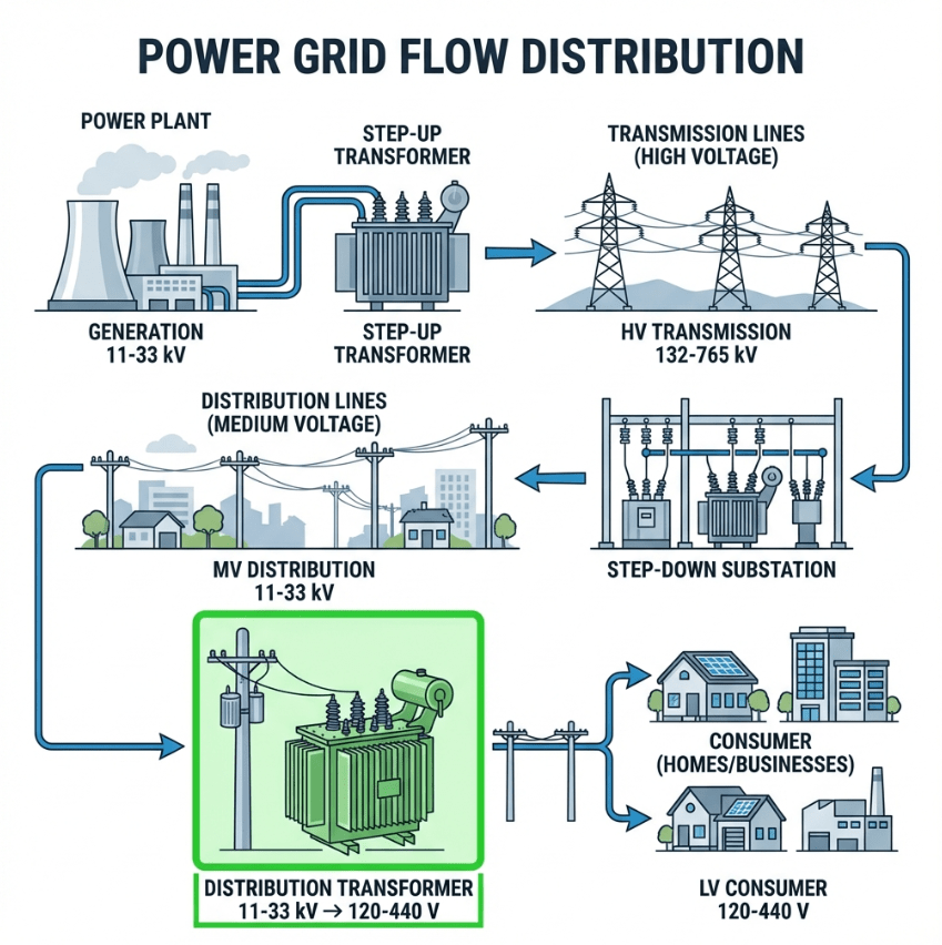
installation environment.Distribution transformers play a vital role in our electrical systems—they’re the final link between the
power grid and your home or business. Without them, the electric energy traveling through transmission
lines at thousands of volts would be completely unusable and extremely dangerous. These transformers
ensure safe and reliable operation of your power supply.In this comprehensive guide, I’ll walk you through everything you need to know about distribution
transformers: how they work, the different types available, how to size them correctly, and lessons
learned from real-world installations.
⚡ Quick Answer
A distribution transformer is the final voltage transformation device in the electric
power distribution system. It steps down medium voltage (typically 11-33 kV) from distribution lines to
the lower voltages (120-440V) used by homes, businesses, and light industrial facilities.
- Voltage: Primary 11-33 kV → Secondary 120-440V
- Capacity Range: 10 kVA to 2,500 kVA (typically under 500 kVA)
- Types: Pole-mounted, pad-mounted, underground, dry-type
- Efficiency: 98-99%, optimized at 50-70% load
- Key Metric: All-day efficiency (not full-load efficiency)
What Is a Distribution Transformer?
A distribution transformer—also called a service transformer—is a step-down transformer that provides the final voltage
reduction in the power distribution network. It converts the medium voltage used in distribution lines
(typically 11 kV, 22 kV, or 33 kV) to the low voltage levels that customers can safely use.
Unlike power transformers that operate in transmission networks
at extremely high voltages, distribution transformers work at the very edge of the grid, close to end
users. They’re the last piece of electrical equipment between the utility and your service panel.
Quick Comparison: Distribution vs Power Transformer
| Feature | Distribution Transformer | Power Transformer |
|---|---|---|
| Position in Grid | Distribution → Customer | Generation → Transmission |
| Voltage Level | 11-33 kV to 120-440V | 33-700 kV |
| Power Rating | 10-2,500 kVA | >500 kVA, typically MVA |
| Efficiency Design | Maximum at 50-70% load | Maximum at 100% load |
| Load Pattern | Variable (fluctuating) | Constant (full load) |
For a detailed comparison, see our guide on power transformer vs distribution
transformer.
How Distribution Transformers Work
Distribution transformers operate on the principle of electromagnetic induction, the
same fundamental principle that governs all transformers.
The Basic Working Principle
- Primary Winding: Connected to the medium-voltage distribution line (e.g., 11 kV)
- Magnetic Core: Made of laminated silicon steel (iron core), concentrates the
magnetic field - Secondary Winding: Outputs low voltage (e.g., 240V) to customers
- Electromagnetic Induction: AC current in the primary creates an alternating
magnetic field, which induces voltage in the secondary
The Transformer Equation
The voltage ratio between primary and secondary is determined by the turns ratio:
Where V₁ = Primary voltage, V₂ = Secondary voltage, N₁ = Number of primary turns, N₂ = Number of
secondary turns.
For example, an 11,000V to 240V transformer has a turns ratio of approximately 46:1.
What a Healthy Transformer Sounds Like
A properly operating distribution transformer produces a gentle, barely audible hum at the line
frequency—60 Hz in North America, 50 Hz in Europe. If you press your hand against the tank (carefully,
with power off), you’ll feel a slight vibration from the laminated core.
buzzing or rattling noise often indicates loose core laminations—a quality issue that can lead to
excessive heating and shortened life.
Types of Distribution Transformers
Distribution transformers come in many varieties to suit different installation environments and load
requirements. Here’s a comprehensive breakdown:
By Installation Method
| Type | Installation | Typical Application | Power Range |
|---|---|---|---|
| Pole-mounted | On utility poles | Rural areas, overhead distribution | 10-167 kVA |
| Pad-mounted | Ground-level concrete pad | Suburban areas, underground lines | 75-2,500 kVA |
| Underground (Vault) | Subsurface vault | Urban areas, aesthetic requirements | 100-2,500 kVA |
| Substation | Indoor or fenced area | Large buildings, industrial sites | 500-10,000 kVA |
Pole-Mounted Transformers
Pole-mounted transformers are the most visible type—you see them riding high on utility poles throughout
residential neighborhoods, especially in areas with overhead power lines.
- Compact and lightweight (for pole mounting)
- Typically single-phase (serving several homes)
- Fused cutout provides protection and visible disconnect
- Common in rural and suburban areas
Pad-Mounted Transformers
The familiar green metal boxes you see on suburban lawns are pad-mounted transformers. They connect to
underground distribution cables, making them ideal for areas where aesthetics matter or where overhead
lines aren’t practical.
- Locked, tamper-proof enclosure
- Bottom cable entry (underground)
- Loop-feed or radial configuration
- Dead-front design for safety
- Common capacity: 75-2,500 kVA

By Number of Phases
| Type | Configuration | Typical Use | Common Ratings |
|---|---|---|---|
| Single-phase | One set of windings | Residential, light commercial | 10-167 kVA |
| Three-phase | Three sets of windings | Commercial, industrial | 75-2,500 kVA |
By Insulation Type
| Type | Cooling/Insulation | Advantages | Best For |
|---|---|---|---|
| Liquid-filled (Oil) | Mineral oil, natural ester | Excellent cooling, high capacity | Outdoor, high-load applications |
| Dry-type | Air, cast resin | No oil, fire-resistant | Indoor, commercial buildings |
For a complete overview of transformer classifications, see our guide on types of transformers.
Key Components of a Distribution Transformer
Understanding the components helps you specify the right transformer and diagnose problems when they
occur. Component requirements are defined by IEEE Standard C57.12.00, which covers general requirements for
liquid-immersed distribution transformers.
| Component | Function | Materials |
|---|---|---|
| Iron Core | Magnetic circuit for flux path | Laminated silicon steel |
| Primary Winding | Connects to MV distribution line | Copper or aluminum wire |
| Secondary Winding | Outputs LV to customers | Copper or aluminum strip |
| Tank | Contains oil, structural support | Steel, powder-coated |
| Insulating Oil | Cooling and insulation | Mineral oil or natural ester |
| Bushings | Primary and secondary terminals | Porcelain or polymer |
| Tap Changer | Adjusts voltage ratio (±2.5% or ±5%) | Mechanical switch |
| Fuses/Arresters | Overcurrent and surge protection | Various |
The Iron Core
The core is made of thin laminations of grain-oriented silicon steel, stacked and bonded or banded
together. The laminations are essential—they reduce eddy current losses that would
otherwise waste energy as heat.
tight bonding. Gaps or misaligned laminations indicate poor manufacturing quality and will lead to
higher losses and noise.
Primary and Secondary Windings
The primary and secondary coils are wound around the core, carefully insulated from each other and from
the core. In distribution transformers:
- Primary windings use finer wire (higher voltage, lower current)
- Secondary windings use heavier conductor—often aluminum or copper ribbon (lower voltage, higher
current)

Connections: Wye vs Delta
Distribution transformers can be connected to the three-phase distribution network in different
configurations, depending on the electrical system design.
Connection Types
| Connection | Symbol | Configuration | Typical Use |
|---|---|---|---|
| Wye (Star) | Y | Phase-to-neutral | Residential, commercial |
| Delta | Δ | Phase-to-phase | Industrial, high-fault areas |
Split-Phase System (North America)
In North America, single-phase distribution transformers typically provide a split-phase
120/240V secondary:
- The secondary winding is center-tapped
- The center tap is grounded (neutral)
- Each end provides 120V to neutral
- Full winding provides 240V end-to-end
This allows homeowners to use both 120V circuits (lighting, receptacles) and 240V circuits (dryers,
ranges, air conditioners) from the same transformer.
European Three-Phase System
In Europe and many other countries, three-phase distribution transformers provide
400Y/230V:
- 230V phase-to-neutral (lighting, receptacles)
- 400V phase-to-phase (heavy loads)
Grounding Considerations
Proper grounding is critical for safety and equipment protection. In wye-connected systems, the neutral
point connects to the transformer tank and to a grounding electrode. This provides a path for fault
current and stabilizes the neutral voltage.
Efficiency and All-Day Efficiency
Efficiency is where distribution transformers differ fundamentally from power transformers—and it’s often
misunderstood.
Why Distribution Transformers Are Different
Unlike power transformers that operate at constant full load, distribution transformers:
- Are energized 24 hours a day
- Experience significant load fluctuations throughout the day
- Rarely operate at full rated load
- Spend most time at 30-70% capacity
Types of Losses
| Loss Type | Description | Behavior |
|---|---|---|
| Iron Loss (Core Loss) | Hysteresis + Eddy current in core | Constant—present when energized |
| Copper Loss (I²R) | Resistive heating in windings | Variable—increases with load squared |
Because iron losses are constant (transformer is always energized) and copper losses vary with load,
distribution transformers are designed to minimize iron losses rather than copper
losses.
All-Day Efficiency: The Key Metric
Standard efficiency measured at full load doesn’t reflect real-world performance for distribution
transformers. Instead, we use all-day efficiency:
📊 Calculation Example: 100 kVA Distribution Transformer
Given: Iron losses = 300W (constant), Copper losses at full load = 1,200W
| Period | Hours | Load | Output (kWh) | Iron Loss (kWh) | Cu Loss (kWh) | Total Loss |
|---|---|---|---|---|---|---|
| Peak | 6h | 80% (80 kW) | 480 | 1.8 | 4.6 | 6.4 |
| Normal | 10h | 50% (50 kW) | 500 | 3.0 | 3.0 | 6.0 |
| Light | 8h | 20% (20 kW) | 160 | 2.4 | 0.4 | 2.8 |
| Total | 24h | – | 1,140 | 7.2 | 8.0 | 15.2 |
All-Day Efficiency = 1,140 ÷ (1,140 + 15.2) = 98.7%
Efficiency Standards
In the United States, the Department of Energy (DOE) sets minimum efficiency standards for
distribution
transformers. These regulations (10 CFR 431), updated in 2016, mandate specific efficiency levels based
on kVA rating
and type.
DOE Minimum Efficiency Requirements (Sample)
| kVA Rating | Single-Phase (Liquid) | Three-Phase (Liquid) |
|---|---|---|
| 15 kVA | 98.60% | – |
| 25 kVA | 98.70% | – |
| 50 kVA | 98.80% | 98.30% |
| 75 kVA | 98.85% | 98.50% |
| 100 kVA | 98.89% | 98.60% |
| 150 kVA | – | 98.70% |
| 300 kVA | – | 98.85% |
| 500 kVA | – | 98.92% |
Note: Actual requirements vary by BIL class and whether dry-type or liquid-filled. See DOE regulations for complete tables.
exceeds current DOE efficiency standards. Non-compliant transformers cannot be legally sold in the
United States.
How to Size a Distribution Transformer
Proper sizing is critical—an undersized transformer will overheat and fail prematurely, while an
oversized unit wastes capital and operates inefficiently.
Sizing Steps
- Determine Load Type: Residential, commercial, or industrial
- Calculate Total Connected Load: Sum of all connected equipment (kVA)
- Apply Demand Factor: Not all loads operate simultaneously
- Add Growth Margin: Typically 20-25% for future expansion
- Select Standard Capacity: Choose the next higher standard size
Basic Formula
📊 Example: Residential Development Sizing
For a new residential development with 50 homes:
- Average connected load per home: 10 kVA
- Demand factor for residential: 0.4 (40%)
- Growth factor: 1.25 (25%)
Required kVA = 50 × 10 × 0.4 × 1.25 = 250 kVA
Select a standard 250 kVA or 300 kVA three-phase transformer.
Standard Capacity Sizes
| Single-Phase | Three-Phase |
|---|---|
| 10, 15, 25, 37.5, 50, 75, 100, 167 kVA | 75, 112.5, 150, 225, 300, 500, 750, 1000, 1500, 2000, 2500 kVA |
For detailed information on transformer ratings, see our guide on transformer rating (kVA and
MVA).
to face overheating problems and premature failures within a few years. The replacement cost—plus the
angry residents without power—far exceeds the savings from the smaller unit.
Installation and Placement
Proper installation is essential for safe and reliable operation of your distribution transformer. A
well-installed unit ensures decades of trouble-free power supply to connected loads.
Pole-Mounted Installation
Requirements:
- Mounting height per utility standards (typically 15-25 feet)
- Fused cutout for protection and visible disconnect
- Arrester for lightning protection
- Grounding wire to pole ground
Pad-Mounted Installation
Requirements:
- Concrete pad sized for transformer footprint
- Minimum clearances from buildings and property lines
- Locking mechanism for security
- Underground cable entry provisions
- Oil containment provisions where required
Placement Considerations
| Factor | Guideline |
|---|---|
| Access | Must allow maintenance access and future replacement |
| Clearance | Minimum distance from buildings, windows, air intakes |
| Ventilation | Adequate airflow for cooling |
| Security | Fencing or locked enclosure where required |
| Aesthetics | Landscaping to screen pad-mounted units |
Common Problems and Troubleshooting
Distribution transformers are generally reliable, but problems do occur. Here’s how to identify and
address common issues:
| Problem | Symptoms | Likely Causes | Solution |
|---|---|---|---|
| Overheating | Hot tank, burning smell, discolored oil | Overload, blocked ventilation, internal fault | Check load, clear obstructions, inspect oil |
| Oil Leaks | Visible oil, dropping oil level | Gasket failure, tank corrosion, bushing seals | Replace gaskets, repaint tank |
| Voltage Problems | Low or high secondary voltage | Wrong tap setting, line voltage issues | Adjust tap changer, check primary voltage |
| Excessive Noise | Loud hum, buzzing, rattling | Loose core, overload, DC component | Tighten bolts, investigate load |
| Complete Failure | No output, tripped fuses | Lightning, internal fault, overload damage | Replace transformer |
🔍 Real-World Case Study
The Problem: Last year, we investigated a transformer failure at a new residential
development. The 100 kVA unit was rated for the calculated load, but within 18 months, it failed
during a summer heat wave.
What Happened: The development had grown faster than expected—additional homes were
added, and many residents installed electric vehicle chargers. The actual load exceeded 130% of
rated capacity during peak hours.
The Symptoms: Residents noticed the transformer running hot to the touch. The oil
discolored from repeated overheating. Eventually, the insulation degraded and an internal fault
destroyed the unit.
The Lesson: Always include growth margin in your sizing calculations—and revisit the
loading as developments expand.
An overloaded distribution transformer runs noticeably hot—the tank too warm to touch comfortably, with
a louder, strained hum. This is your warning sign before failure.
Frequently Asked Questions
transformer?
The main differences are voltage level, capacity, and position in the power system:
- Power transformers operate at high voltage (>33 kV) in transmission
networks, rated above 500 kVA, designed for maximum efficiency at full load. - Distribution transformers operate at medium/low voltage (<33 kV), rated up
to 2500 kVA, designed for maximum efficiency at partial loads.
For residential service, single-phase transformers are typically 25-167 kVA. For commercial and
industrial applications, three-phase units range from 75 to 2500 kVA.
Distribution transformers are energized 24/7 but experience varying loads throughout the day.
All-day efficiency captures the true energy performance over a full day, accounting for both
constant iron losses and variable copper losses.
A well-maintained distribution transformer typically lasts 25-40 years. Factors affecting
lifespan include loading history, environmental conditions, and maintenance practices.
Liquid-filled (oil) transformers are generally restricted to outdoor use due to fire risk.
Dry-type transformers are specifically designed for indoor installations in schools, hospitals,
commercial buildings, and data centers.
A pad-mounted transformer is a ground-level distribution transformer mounted on a concrete pad.
It connects to underground cables and features a locked enclosure for safety and security.
They’re common in suburban areas where underground power distribution is used.
Warning signs include:
- Excessive heating (tank too hot to touch)
- Unusual sounds (loud humming, buzzing, popping)
- Visible oil leaks
- Discolored or burnt-smelling oil
- Flickering lights or voltage fluctuations
Key standards include:
- IEEE C57.12 –
General requirements for liquid-immersed transformers - DOE Efficiency Standards – Mandatory efficiency requirements in the US
- IEC 60076 – International transformer standards
📌 Key Takeaways
- Distribution transformers are the final voltage step-down in the power grid (11-33
kV → 120-440V) - Types: Pole-mounted, pad-mounted, underground, single-phase, three-phase,
liquid-filled, dry-type - Efficiency: Designed for maximum efficiency at 50-70% load—not full load
- All-day efficiency is the key metric, accounting for 24-hour operation with varying
loads - Sizing: Include demand factor and 20-25% growth margin in calculations
- Single-phase for residential; three-phase for
commercial/industrial - Proper installation and regular inspection extend life to 30+
years - Warning signs of failure include overheating, unusual noise, and oil leaks
Need Help Selecting the Right Distribution Transformer?
Our engineering team has 15+ years of experience in transformer manufacturing. Whether you’re designing a
new residential development, upgrading commercial infrastructure, or specifying industrial distribution,
we can help.
References
- IEEE C57.12.00 – General Requirements for
Liquid-Immersed Distribution, Power, and Regulating Transformers - Distribution Transformer –
Wikipedia - DOE – Energy Conservation Standards for Distribution Transformers
- Electrical4U – Distribution Transformer and All-Day Efficiency
- Harlow, J.H. (2012). Electric Power Transformer Engineering, Third Edition. CRC Press.