
In my years working at a transformer manufacturing facility, I’ve seen customers order the wrong type of
transformer more often than you’d expect. The most common mistake? Specifying a distribution transformer
for a substation application—or ordering a massive power transformer when a compact pole-mounted unit
would do the job perfectly.
Understanding the difference between power transformers and distribution
transformers isn’t just academic—it’s essential for proper system design, efficiency, and
avoiding costly replacements.
⚡ Quick Answer
Power transformers operate at high voltages (typically >33 kV) in transmission networks
and are rated above 500 kVA. They’re designed for maximum efficiency at 100% load.
Distribution transformers operate at lower voltages (<33 kV) and deliver electrical
energy directly to end consumers. They’re optimized for “all-day efficiency” at 50-70% load.
The key difference lies not just in size or voltage, but in how they’re designed: power
transformers minimize copper losses for constant full-load operation, while distribution
transformers minimize iron losses because they run 24/7 with fluctuating loads.
Quick Comparison Table
Before diving into details, here’s an at-a-glance comparison of power transformers and distribution
transformers:
| Feature | Power Transformer | Distribution Transformer |
|---|---|---|
| Voltage Level | 33 kV – 400+ kV (High Voltage) | 230 V – 33 kV (Medium/Low Voltage) |
| Power Rating | > 500 kVA, typically MVA | 3 – 500 kVA |
| Location in Grid | Generation & Transmission | Distribution to End Users |
| Primary Function | Step-up & Step-down | Mostly Step-down |
| Loading Pattern | Constant (100% load) | Variable (fluctuating) |
| Efficiency Design | Maximum at 100% load | Maximum at 50-70% load |
| Size | Large & Heavy | Smaller & Compact |
| Installation | Ground-mounted (substations) | Pole or Pad-mounted |
| Cooling Method | ONAN, ONAF, OFAF, OFWF | ONAN, Dry-type |
| Relative Cost | Higher | Lower |
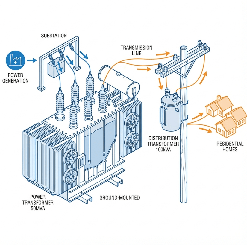
What Is a Power Transformer?
A power transformer is a high-capacity electrical device used to
transfer electrical energy between circuits in transmission networks. These transformers handle the highest
voltages in the power system—from generation plants through transmission substations.
Key Characteristics:
- Voltage Range: 33 kV to 400+ kV (some transmission transformers exceed 700 kV)
- Power Rating: Typically 5 MVA to 500+ MVA
- Function: Both step-up (at generation) and step-down (at substations)
- Operation: Continuous full-load operation, 24/7
Where You’ll Find Them:
- Power Generation Stations – Step-up transformers increase generator voltage from 11-25
kV to transmission levels (132-400 kV) - Transmission Substations – Step-down transformers reduce voltage for sub-transmission
- Grid Interconnection Points – Tie different voltage levels together
the same power), which in turn reduces I²R losses in transmission lines. This is why power transformers step
up voltage at generation and step down at consumption points.
What Is a Distribution Transformer?
A distribution transformer is a step-down transformer that
performs the final voltage transformation in the distribution network. It converts medium-voltage
electricity (typically 11 kV or 6.6 kV) to the low voltages used by homes and businesses—typically 240V or
120V.
Key Characteristics:
- Voltage Range: Primary 11-33 kV, Secondary 230-440V
- Power Rating: 3 kVA to 500 kVA (per IEEE 141 definition)
- Function: Step-down only (in almost all cases)
- Operation: Variable load throughout the day
Common Types:
| Type | Installation | Typical Application |
|---|---|---|
| Pole-mounted | On utility poles | Residential areas with overhead lines |
| Pad-mounted | Ground-level concrete pad | Suburban areas, underground distribution |
| Underground | Subsurface vault | Urban areas, aesthetic requirements |
| Single-phase | Any of above | Residential, light commercial |
| Three-phase | Any of above | Commercial, industrial |
Key Differences Between Power and Distribution Transformers
Now let’s examine the specific technical differences that distinguish these two transformer types.
1. Voltage Ratings
The most obvious difference is the voltage level at which each operates.
| Aspect | Power Transformer | Distribution Transformer |
|---|---|---|
| Primary Voltage | 33 kV – 700 kV | 11 kV – 33 kV |
| Secondary Voltage | 33 kV – 220 kV | 230 V – 440 V |
| Voltage Class | High Voltage (HV), Extra High Voltage (EHV) | Medium Voltage (MV), Low Voltage (LV) |
2. Power Rating (The IEEE 141 Definition)
According to IEEE
141 (IEEE Recommended Practice for Electric Power Distribution for Industrial Plants):
“The distribution type covers the range of 3 to 500 kVA; the power type covers all ratings above 500 kVA.”
This 500 kVA threshold is also recognized in IEEE C57.12.00, the general standard for liquid-immersed
transformers. While some manufacturers use slightly different cutoffs, the 500 kVA line remains the industry
benchmark.
| Rating Class | Power Transformer | Distribution Transformer |
|---|---|---|
| Typical Range | 5 MVA – 500+ MVA | 3 kVA – 500 kVA |
| Common Sizes | 10, 20, 31.5, 50, 100 MVA | 25, 50, 100, 200, 315 kVA |
For detailed information on transformer ratings, see our guide on transformer rating (kVA and
MVA).
3. Efficiency and Load Design
This is perhaps the most important—and most misunderstood—difference between power and distribution
transformers.
Power Transformer Efficiency:
- Designed for maximum efficiency at 100% load
- Operates at constant full load (or near it) 24/7
- Efficiency range: 95% to 99.5%
- Iron losses and copper losses are matched at peak load
Distribution Transformer Efficiency:
- Designed for maximum efficiency at 50-70% load
- Operates with significant load fluctuations throughout the day
- Uses the concept of All-Day Efficiency
evening), low at night. Standard “efficiency” measured at full load doesn’t reflect real-world
performance.All-Day Efficiency = (Total Output Energy in 24h) ÷ (Total Input Energy in 24h)This metric accounts for periods of light load when iron (core) losses dominate, and periods of heavy
load when copper losses dominate.
📊 All-Day Efficiency Calculation Example
Consider a 100 kVA distribution transformer with:
- Iron losses (constant): 300 W
- Copper losses at full load: 1,200 W
| Period | Hours | Load | Output (kWh) | Cu Loss (W) | Total Loss (kWh) |
|---|---|---|---|---|---|
| Peak | 6h | 80% (80 kW) | 480 | 768 W | 6.4 |
| Normal | 10h | 50% (50 kW) | 500 | 300 W | 6.0 |
| Light | 8h | 20% (20 kW) | 160 | 48 W | 2.8 |
| Total | 24h | – | 1,140 kWh | – | 15.2 kWh |
All-Day Efficiency = Output ÷ (Output + Losses) = 1,140 ÷ (1,140 + 15.2) =
98.7%
Note: The standard efficiency at 50% load would be approximately 99.4%, but all-day efficiency gives
a more realistic picture of actual energy consumption.
| Design Aspect | Power Transformer | Distribution Transformer |
|---|---|---|
| Efficiency Target | Peak at 100% load | Peak at 50-70% load |
| Loss Optimization | Copper losses minimized | Iron losses minimized |
| Core Design | Higher flux density, near saturation | Lower flux density |
| Always Energized? | Yes, at constant load | Yes, but load varies |
4. Core Design and Flux Density
Power transformers are designed to operate at higher flux density, closer to the saturation
point of the B-H curve. This allows designers to reduce core mass while maintaining performance at full
load.
Distribution transformers operate at lower flux density as a compromise between peak efficiency and all-day
efficiency. Since they’re always energized (even at no load), minimizing core losses is critical.
5. Losses: Iron vs Copper
Understanding transformer losses helps explain why these two types are designed so differently.
| Loss Type | Power Transformer | Distribution Transformer |
|---|---|---|
| Iron Loss (Core) | Constant; minimized through high-quality core steel | Critical—transformer is always energized |
| Copper Loss (I²R) | Dominant at full load; design priority | Variable with load; less critical |
| Design Philosophy | Match Fe and Cu losses at peak | Minimize Fe losses for all-day efficiency |
“Power transformers are designed such that copper losses are minimal. However, a distribution transformer is
always online and operated at loads less than full load for most of time. Hence, it is designed such that
core losses are minimal.”— Electrical Engineering Portal
6. Insulation Level
Power transformers require much higher insulation levels due to higher operating voltages, higher fault
current exposure, and greater electrical stress during surges and lightning.
| Insulation Aspect | Power Transformer | Distribution Transformer |
|---|---|---|
| BIL (Basic Impulse Level) | Higher (150-1800 kV) | Lower (30-150 kV) |
| Insulation Material | Multi-layer oil-impregnated paper | Standard oil-paper or dry-type resin |
| Withstand Voltage | Higher short-circuit and surge capability | Adequate for distribution-level stresses |
7. Cooling Methods
Larger power ratings generate more heat, requiring more sophisticated cooling systems.
| Cooling Code | Description | Power Transformer | Distribution Transformer |
|---|---|---|---|
| ONAN | Oil Natural, Air Natural | Small units only | Most common |
| ONAF | Oil Natural, Air Forced (fans) | Common | Occasional |
| OFAF | Oil Forced, Air Forced | Large units | Rare |
| OFWF | Oil Forced, Water Forced | Very large units | Never |
| Dry-type | Air-cooled, no oil | Rare | Common for indoor |
8. Physical Size and Weight
Power transformers are significantly larger and heavier:
| Aspect | Power Transformer | Distribution Transformer |
|---|---|---|
| Size | Large—may require special transport | Compact—fits on utility poles |
| Weight | 10-400+ tons | 50 kg – 5 tons typical |
| Transportation | Special permits, route planning | Standard trucks |
| Foundation | Reinforced concrete pad required | Pole or simple pad |
9. Installation Location
The location in the power system defines the transformer type needed.
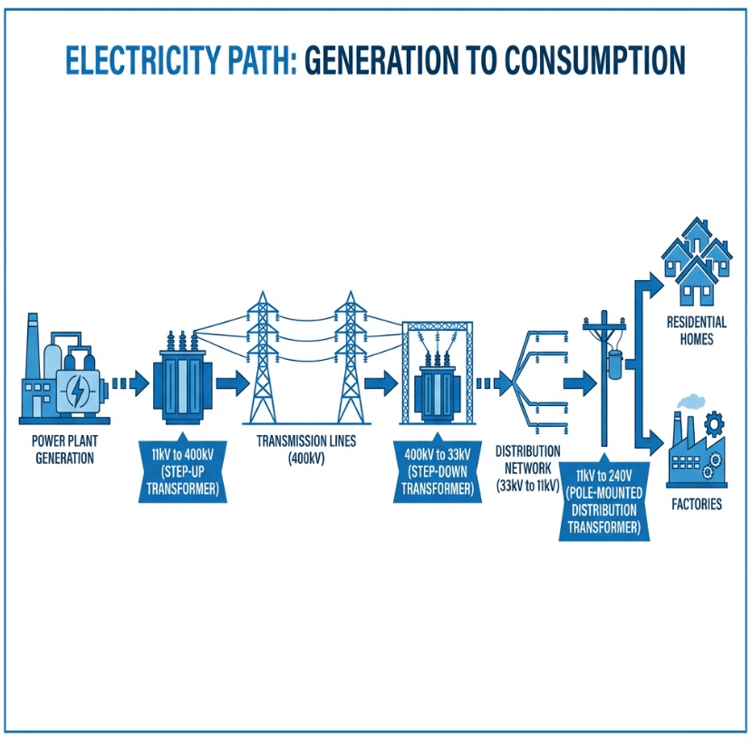
Power Transformer Locations:
- Power generation stations
- Transmission substations (220/132 kV, 132/66 kV, 66/33 kV)
- Grid interconnection points
- Large industrial facilities (captive power)
Distribution Transformer Locations:
- Utility poles (residential areas)
- Ground-level pads (suburban areas)
- Underground vaults (urban areas)
- Building basements (commercial/industrial)
- Near the point of consumption
10. Types and Varieties
Transformers based on their application in the power system come in different varieties.
Distribution transformers have many more variations due to their diverse end-use requirements:
| Category | Power Transformer | Distribution Transformer |
|---|---|---|
| Phase Configuration | Almost always 3-phase | Single-phase and 3-phase |
| Mounting Style | Ground-mounted only | Pole, pad, underground, indoor |
| Cooling Medium | Oil-filled dominant | Oil-filled and dry-type |
| Design Variants | Autotransformer, phase-shifting | Conventional, autotransformer |
For a complete overview of transformer classifications, see our guide on types of transformers.
11. Voltage Regulation
Voltage regulation indicates how well a transformer maintains output voltage as load changes.
| Aspect | Power Transformer | Distribution Transformer |
|---|---|---|
| Typical Regulation | 2-5% | 4-10% |
| Tap Changer | OLTC (On-Load Tap Changer) common | NLTC (No-Load Tap Changer) typical |
| Regulation Priority | Critical for grid stability | Less critical, fixed taps sufficient |
Power transformers often include on-load tap changers (OLTC) that adjust voltage in
real-time without interrupting the load. Distribution transformers typically use off-load tap
changers that require de-energizing before adjustment.
12. Impedance (%Z)
Impedance affects fault current levels and voltage regulation.
| Aspect | Power Transformer | Distribution Transformer |
|---|---|---|
| Typical %Z | 8-15% | 3-6% |
| Design Goal | Limit fault current, protect windings | Lower losses, better regulation |
| Parallel Operation | Must match %Z closely | Less critical |
Higher impedance in power transformers helps limit fault currents in high-power transmission systems.
Distribution transformers use lower impedance to minimize losses in variable-load conditions.
How to Choose Between Power and Distribution Transformers
Selecting the right transformer type isn’t always straightforward. Here’s a decision guide based on my
experience:

Choose a POWER TRANSFORMER if:
- Operating voltage exceeds 33 kV
- Power rating exceeds 500 kVA
- Located at a generation plant or transmission substation
- Continuous full-load operation is expected
- Long-distance power transmission is involved
Choose a DISTRIBUTION TRANSFORMER if:
- Operating voltage is below 33 kV
- Power rating is below 500 kVA
- Supplying power directly to end consumers
- Load varies significantly throughout the day
- Installation is on a pole, pad, or underground vault
for a small industrial substation because the secondary voltage was 440V. But the 24/7 constant high-load
operation meant they needed a power transformer design with better cooling and higher efficiency at full
load. Always consider the loading pattern, not just the voltage.
Common Mistakes When Selecting Transformers
From my experience in transformer manufacturing, here are the most common selection errors:
❌ Mistake 1: Using Only kVA Rating to Decide
The Error: Assuming anything under 500 kVA is automatically a distribution transformer.
Reality: A 300 kVA transformer for a small substation operating at constant full load
may need power transformer characteristics (better cooling, optimized copper losses).
❌ Mistake 2: Ignoring Load Pattern
The Error: Not considering whether the load is constant or variable.
Reality: A data center with 24/7 constant load needs different efficiency optimization
than a residential area with peak-and-valley demand.
❌ Mistake 3: Wrong Insulation Level for the Environment
The Error: Specifying standard insulation in high-lightning or high-pollution areas.
Reality: Distribution transformers in coastal or industrial areas may need enhanced
insulation despite operating at lower voltages.
substation. The transformer was properly rated for the voltage and load, but within months, they
experienced voltage regulation issues and excessive heating during peak production hours.The problem? The transformer was designed for the variable loads typical of residential distribution—not
for the constant high-load operation of an industrial facility. We had to replace it with a power-class
design optimized for full-load efficiency.A properly sized power transformer at full load runs warm but stable—you can feel the slight
vibration of the laminations and a gentle warmth from the tank. An undersized or wrongly-specified
transformer, by contrast, runs hot to the touch and produces a noticeably louder hum as it struggles
to meet demand.
Frequently Asked Questions
Technically yes, but it would be impractical. Power transformers are designed for high-voltage,
constant-load applications. Using one for distribution would be:
- Over-engineered for the voltage and load requirements
- Inefficient at the partial loads typical of distribution
- Costly both in capital and operating expenses
- Oversized for typical pole or pad mounting
The main difference is their position and function in the power system:
- Power transformers operate in transmission networks at high voltages (>33 kV),
handling step-up and step-down between generation and distribution - Distribution transformers operate at the end of the distribution network at
lower voltages (<33 kV), delivering power directly to consumers
Distribution transformers experience significant load fluctuations—high during peak hours, low at
night. Standard efficiency measured at full load doesn’t reflect real-world energy consumption.
All-day efficiency measures total energy efficiency over 24 hours, providing a more accurate picture
of actual losses and operating costs.
According to IEEE 141 (IEEE Recommended Practice for Electric Power Distribution for
Industrial Plants):
- Distribution transformers: 3 to 500 kVA
- Power transformers: Above 500 kVA
This threshold is recognized industry-wide, including in NETA testing standards.
It depends on how you measure:
- Power transformers have higher instantaneous efficiency at full load (up to
99.5%) - Distribution transformers are optimized for all-day efficiency at partial loads
(50-70%)
For constant-load applications, power transformers are more efficient. For variable-load
applications, distribution transformers deliver better overall energy performance.
Not effectively. Each type is optimized for its specific application:
- Core design and flux density differ
- Loss optimization priorities differ
- Cooling systems differ
- Insulation levels differ
Using the wrong type leads to poor efficiency, potential overheating, and shortened equipment life.
📌 Key Takeaways
- Power transformers operate at high voltage (>33 kV) in transmission networks, rated
above 500 kVA, designed for maximum efficiency at 100% load - Distribution transformers operate at lower voltage (<33 kV) to supply end
consumers, rated 3-500 kVA, optimized for all-day efficiency at partial loads - IEEE 141 defines the 500 kVA threshold between power and distribution class
- Power transformers minimize copper losses (constant full load); distribution
transformers minimize iron losses (24-hr energized, variable load) - Always consider voltage level, power rating, AND loading
pattern when selecting transformer type - The wrong choice leads to poor efficiency, overheating, and premature failure
🔧 Need Help Selecting the Right Transformer?
Our engineering team has 15+ years of experience in transformer manufacturing. Whether you’re designing a
substation, upgrading distribution infrastructure, or need guidance on specifications, we can help you
choose between power and distribution transformers for your specific application.
References
- IEEE 141 – IEEE
Recommended Practice for Electric Power Distribution for Industrial Plants - IEEE
C57.12.00 – General Requirements for Liquid-Immersed Distribution, Power, and Regulating
Transformers - Electrical4U – Distribution Transformer and All-Day Efficiency
- Electrical Engineering Portal – Difference between Power Transformer and Distribution Transformer